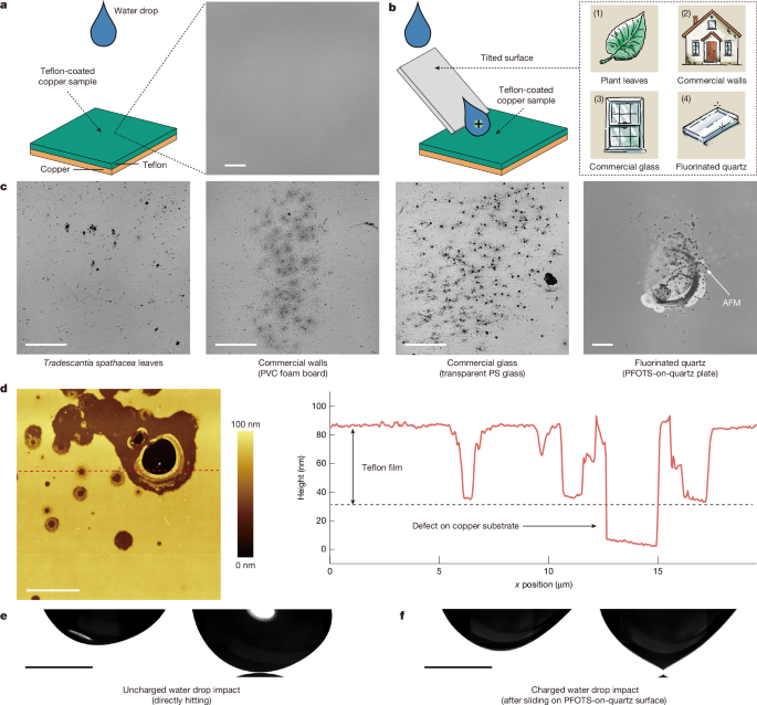
MainMetal corrosion is a serious economic and safety issue facing modern society17,18,19. Outdoor metal products are particularly vulnerable to water drops from rain, dew, ocean waves and melting snow20,21,22,23,24,25. Using anticorrosion coatings is the simplest and most effective method; however, these coatings inevitably degrade over time26,27. Conventional understanding attributes the coating failure induced by water drops mainly to two mechanisms: physical abrasion caused by moving drops28,29,30 and chemical degradation from acidic substances and pollutants in the drops31,32,33.In recent years, it has been demonstrated that water drops moving over insulating solid surfaces can spontaneously acquire a charge and deposit an opposite charge to the surface1,2,3,4,5,6,7,8,9. Hereby the electric potential of charged water drops can reach several thousand volts14,15,16, depending on the specific materials involved and the thickness of the insulating layer. Here we show a previously overlooked corrosion mechanism induced by water drops: spontaneously charged water drops, whether hitting or sliding, can cause strong electric fields, leading to dielectric breakdown and cause degradation of the protective coating (polymer or oxide layer), thereby allowing subsequent corrosion of the metal substrate. Typically, ‘degradation’ is more commonly used to describe the damage to coatings. However, according to the International Union of Pure and Applied Chemistry (IUPAC), ‘corrosion’ also refers to materials other than metals, such as ceramics and polymers34. In the following discussion, we use ‘corrosion’ to refer to the damage of both coatings and metals.Spontaneously charged water drops induce corrosionAs a reference, we studied electrically neutral water drops directly falling onto a sample (Fig. 1a). 35-μl water drops were continuously released at 12-s intervals from a height of 4 cm and directly dropped onto a Teflon-coated copper sample. Usually, water drops in nature, such as rainwater, are not distilled water but contain some salt, whose concentration depends on local environmental conditions35,36. In our experiments, the water drops contained 1 mM NaCl. We made the sample by sputtering a 35-nm-thick layer of copper onto a smooth quartz plate. Then a 60-nm-thick Teflon film was deposited by dip-coating onto the copper substrate from a 1-wt% Teflon AF 1600 solution. Finally, the samples were annealed at 160 °C under vacuum for 24 h. We chose the Teflon coating because it is chemically robust. The samples were tilted by 10° so that water drops ran off before the subsequent drops hit the surface. We analysed the sample surface by reflection mode confocal microscopy after 3,000 water drops had directly hit it. This analysis revealed flat and smooth surfaces. There was no notable difference in the morphology of the sample surface before or after the drop hit it.Fig. 1: Corrosion induced by spontaneously charged water drops.a, Schematic of a water drop directly hitting a 60-nm-thick Teflon film on copper. Reflection mode confocal microscopy (LSM 880, Carl Zeiss) image of the surface morphology after 3,000 water drops. The image was recorded in reflection mode with an Ar-ion laser at 488 nm. The surface morphology of the impact area remains flat and smooth. b, Schematic diagram of a water drop sliding on a tilted surface to acquire charge and then hitting a Teflon-coated copper sample. As surface we used plant leaves (1), commercial walls (2), commercial glass (3) or fluorinated quartz (4). c, Reflection mode confocal microscopy images of the surface morphology of the Teflon-coated copper sample after impact of 3,000 charged water drops. In contrast to the direct impact of neutral drops, every image shows corrosion of the sample surface. Different images represent different tilted surfaces used to charge water drops. From left to right: Tradescantia spathacea leaves, PVC foam board, transparent PS glass and lab-prepared fluorinated quartz (PFOTS coated on quartz plate). d, AFM (Dimension Icon, Bruker) image of the surface morphology for the fourth image in c. We plotted a line profile along the dashed red line. The corrosion pattern corresponds to hole-like defects. The depth of the defect is in the range of several nanometres and even exceeds the Teflon film thickness into the underlying copper substrate. e,f, Side-view high-speed camera images of uncharged and charged water drops before hitting the Teflon-coated copper. The bottom of the uncharged water drops from direct impact experiments always retains a smooth arc shape. The bottom of charged water drops forms a cone shape when approaching the Teflon-coated copper surface. Scale bars, 100 μm (a,c); 5 μm (d); 1 mm (e,f).Source dataTo demonstrate that the charge caused by slide electrification in water drops induces corrosion, while keeping other conditions unchanged, we let water drops slide down four different 50° tilted surfaces before they fell onto the Teflon-coated copper sample. We selected four surfaces that are representative of many surfaces we encounter every day (Fig. 1b). A plant leaf: Tradescantia spathacea leaves (Fig. 1b (1)). A construction material: polyvinyl chloride (PVC) foam boards of 3 mm thickness (Fig. 1b (2)). A window: polystyrene (PS) glass of 2 mm thickness (Fig. 1b (3)). PVC and PS were purchased from a local hardware store. A widely used hydrophobic surface coating: perfluorooctadecyltrichlorosilane (PFOTS) coated on quartz (Fig. 1b (4)). The PFOTS was prepared on a 1-mm-thick quartz plate by chemical vapour deposition (CVD). Depending on the specific tilted surface, water drops acquired a charge between 0.2 and 2 nC after sliding for 4 cm (Extended Data Fig. 1). Then the water drops slid off the tilted surfaces and hit the Teflon-coated copper sample, dropping from a height of 5 mm. The reflection mode confocal microscopy images showed corrosion patterns in all four cases after the impact of 3,000 water drops (Fig. 1c). The corrosion pattern was located in the area of the drops’ initial contact with the sample surface. Atomic force microscopy (AFM) revealed that the charged water drop led to the hole-like defects on the sample surface (Fig. 1d). Both the Teflon film and the underlying copper substrate were corroded.To gain better insight into the cause of corrosion, water drops hitting the Teflon-coated copper sample were imaged from the side with a high-speed camera. Electrically neutral drops showed no sign of deformation in the drop shape before contact with the sample surface; these drops either came out of a grounded metal needle (Fig. 1e and Supplementary Video 1) or had slid over a grounded PFOTS layer on indium tin oxide (ITO) (Extended Data Fig. 2). By contrast, when water drops charged by sliding over a PFOTS-on-quartz surface and then came close to the sample surface, the bottom of the drop elongated and formed a cone shape (Fig. 1f, Extended Data Fig. 3 and Supplementary Video 2). This behaviour is similar to the formation of a Taylor cone in the electrospraying process, in which the electrostatic force acting on the liquid surface overcomes the surface tension, thus causing deformation37,38. We attribute this cone formation of the drop to the strong electric field generated when approaching the sample, which typically serves as an indicator of sample surface corrosion.To demonstrate that the charge-induced corrosion is not restricted to Teflon-coated copper surfaces, PS films (192 kg mol−1) of thickness 60 nm, 200 nm, 1 μm and 5 μm were prepared on copper, as well as a 200-nm-thick PS film on sputtered gold by dip-coating and a 60-nm-thick SiO2 sputter-coated film on gold. Surface corrosion similar to that shown in Fig. 1c was observed at the initial contact area after 3,000 charged drops had hit (Extended Data Fig. 4). We conclude that corrosion induced by spontaneously charged water drops on metals coated with an insulating layer is a general phenomenon.Water drop dischargeGiven that drop cone formation is strongly correlated with discharge phenomena, we placed a current amplifier at three distinct positions and monitored the respective charge changes (Fig. 2). A drop sliding 4 cm down a tilted PFOTS-on-quartz surface acquired a charge of +2.0 ± 0.021 nC (position 1, Fig. 2 inset blue bar and Extended Data Fig. 5a). When the drop hit the 60-nm Teflon-on-copper surface, most of the charge was transferred into the copper layer, +1.8 ± 0.022 nC, (position 2, Fig. 2 inset green bar and Extended Data Fig. 5b). At position 3, after leaving the Teflon-on-copper surface, the drop retained only +0.016 ± 0.003 nC (Fig. 2 inset orange bar and Extended Data Fig. 5c). These results indicate that the highest charge is exchanged between the drop and copper substrate at the moment of impact. We conclude that corrosion of the sample is caused by the discharge of water drops.Fig. 2: Charge measurement.Schematic of the charge measurement. Water drops fall from the syringe tip onto a tilted surface (α = 50°), here a PFOTS on quartz. Drops slide down a length L = 4 cm to reach the edge and then fall onto a Teflon-coated copper sample, which is slightly tilted to enable drop roll-off. A current amplifier (response time: 0.8 ms, FEMTO DDPCA-300), placed at three distinct positions, was used to monitor the respective charge changes. In position 1, a tungsten wire (0.7 mm in diameter) was used, which acts as an electrode connected to the current amplifier. Here a charge of +2.0 ± 0.021 nC (inset blue bar) generated by drop slide electrification is detected when the drop makes contact with the tungsten wire. In position 2, the copper substrate is directly connected to the current amplifier. In this case, we detected the charge transfer of +1.8 ± 0.022 nC (inset green bar) when the drop hits the sample. In position 3, the drop rolls off the sample and then makes contact with the tungsten electrode. Almost no charge (+0.016 ± 0.003 nC) is detected remaining in the drop (inset orange bar). The set-up is purged continuously with an ionizing air blower (Aerostat PC ionizing air blower, Simco-Ion) to neutralize the PFOTS surface between two subsequent drops to ensure that each water drop has the same slide electrification effect on the PFOTS on quartz. The bar chart shows the average and standard deviation of 20 measurements of drop charge obtained at three positions.Source dataWater drop discharge modelWe suggest that discharge is caused by dielectric breakdown of the insulating coating when the water drop approaches the sample surface. When the electric field strength between two electrodes exceeds the dielectric strength of the medium, dielectric breakdown occurs. Charge is transferred from one electrode to another through the medium. In our case, the water drop and the metal substrate, respectively, act as two electrodes (Fig. 3a). The water drop accumulates a positive charge through slide electrification. In the metal substrate, an equivalent amount of negative image charge is induced. Together, the positive charge in the water drop and the negative charge in the metal substrate create an electric field. As the drop approaches the surface, the electric field increases. To estimate the electric field during approach, the water drop was assumed to act as a conductive sphere of radius R opposite to a conductive wall formed by the metal. Then the capacitance of the water drop changes with distance as C = 4πεε0R(1 + 0.5ln(1 + R/h)) (ref. 39). Here, ε is the relative permittivity of the intervening medium, ε0 is the vacuum permittivity and h is the distance from the surface of the metal substrate to the bottom of the water drop. In the experiment, R is 2.0 mm. When the distance is large, the capacitance should be calculated using the relative permittivity of air; at impact, it is more appropriate to use the relative permittivity of the coating (Fig. 3b). According to U = Q/C (U: voltage between the water drop and metal, Q: charge of the water drop), the change in electric field strength can be estimated, E = U/h, as the water drop approaches the surface (Fig. 3c). The charged water drop leads to breakdown of up to a film thickness of about 10 μm for Teflon or about 50 μm for PS. This corresponds to dielectric strengths of 60 kV mm−1 and 19 kV mm−1, respectively. Thus, the calculations demonstrate that a water drop carrying approximately nC charge can break down most micrometre-thick insulating coatings (Extended Data Fig. 6). On the basis of Joule heating effect estimation, the damage caused to the Teflon film by a single charged drop is in the sub-μm range (Supplementary Information Discussion 1). The accumulation of Joule heating-induced localized damages (Extended Data Fig. 7) led to metal exposure and increased corrosion risk.Fig. 3: Mechanism of water drop discharge.a, Schematic of a charged water drop over a metal substrate. b, Capacitance of a water drop C versus the distance h calculated for air (ε = 1) and a typical polymer (ε = 3). The true capacitance is described by ε = 1 for large distances (main medium is air) and ε = 3 for short distances (main medium is a polymer). c, Electric field strength between the charged water drop and the copper substrate versus distance. A water drop containing a charge of 2 nC can cause dielectric breakdown at a distance of about 10 μm for a Teflon-coated (dielectric strength, 60 kV mm−1) or about 50 μm for a PS-coated (dielectric strength, 19 kV mm−1) metal substrate.Our estimation of electric field strength represents a lower limit. Before the water drop touches the sample, it forms a conical structure at the bottom (Fig. 1f). This deformation would lead to a lower effective radius of curvature and thus a locally higher electric field. A more complete analysis of dielectric breakdown needs to take into consideration the coating thickness. Rather than assuming a constant dielectric strength, in reality, the dielectric breakdown strength of a coating is known to depend on the thickness40.Products of corrosionAs well as morphological damage, dielectric breakdown can cause chemical changes within the coating, resulting in new substances forming. Confocal microscopy images of a 200-nm-thick PS film on copper after 3,000 water drop impacts (Fig. 4a) showed the appearance of rough regions on the smooth PS surface in reflection mode. The fluorescence mode further revealed that some rough regions emitted fluorescence on 488-nm excitation, with broad emission spectra covering 520–680 nm (Extended Data Fig. 8). PS contains benzene rings and does not form a conjugated π-electron cloud system. Therefore the observed fluorescence does not originate from the PS but from the products of a reaction that have such a π-electron cloud system.Fig. 4: Products created by charged-drop impacts.a, Reflection and fluorescence confocal microscopy images of a 200-nm-thick PS film after impact of 3,000 charged water drops generated on a PFOTS-on-quartz plate. Excitation: 488 nm; fluorescence detection: 517–696 nm. b, AFM topography and nano-IR response of a region containing reaction products and normal PS. Nano-IR images were recorded by PiFM at 1,496 cm−1 (absorption of PS) and 1,641 cm−1. c, IR spectra were recorded in PiFM mode by varying the wavenumber of the IR light between 1,400 and 1,900 cm−1. Blue and red spectra correspond to the reaction products (blue triangle in b) and pristine PS regions (red triangle in b), respectively. Reaction products exhibit strong IR signals between 1,600 and 1,700 cm−1, suggesting the presence of C=C or C=O double bonds. d, SEM image and EDS analysis of 60-nm Teflon-coated Cu foil after 50,000 impacts of charged drops (35 µl 10 mM NaCl). Region 1 is an uncorroded area and regions 2 and 3 are corroded. EDS results showed a loss of fluorine and carbon, an increase in oxygen and the presence of chlorine in area 2, indicating that the corrosion products are mainly oxides with some chlorides. e, Raman spectra indicated that area 2 mainly contained basic copper chloride, whereas area 3 mainly contained cuprous oxide. f, XRD analysis of the corroded area. The diffraction peaks were dominated by pure copper, with weaker peaks corresponding to cuprous oxide and basic copper chloride based on comparison with the Powder Diffraction File (PDF) database. Because the X-ray beam was 1 mm wide, it covered both the corroded areas and the surrounding Cu. Scale bars, 200 µm (a); 1 µm (b); 1 mm (d). a.u., arbitrary units.Source dataAFM-based nano-infrared (IR) analysis provided further characterization of the reaction products in the PS films41,42. The topography image showed a roughened region corresponding to reaction products surrounded by PS (Fig. 4b). Nano-IR imaging at 1,495 cm−1, corresponding to the aromatic C=C stretching of PS, showed lower absorption in the roughened area than in the surroundings, whereas imaging at 1,641 cm−1 produced an inversion of the contrast, indicating chemical bonds not present in PS. IR spectra recorded from the roughened and flat areas (Fig. 4c) both exhibited the characteristic PS peaks at 1,458 cm−1 and 1,495 cm−1, corresponding to the aromatic C=C stretching of PS (ref. 42). However, only the roughened area showed a distinct broad IR absorption band between 1,600 cm−1 and 1,700 cm−1, a range associated with the double-bond stretching vibration of C=C and carbonyls C=O (refs. 43,44). These two types of double bond and the benzene rings possibly form a conjugated π-electron cloud system, thus having fluorescent properties.To demonstrate corrosion under broader conditions, we used commercial copper foil instead of the sputtered copper on quartz and coated with a 60-nm-thick Teflon film by dip-coating. Charged drops damaged the coating through dielectric breakdown. Electrochemical impedance spectroscopy (EIS) results consistently demonstrated that the initially excellent barrier properties of the coating were degraded after 10,000 charged-drop impacts (Extended Data Fig. 9 and Extended Data Table 1). Under the same salt concentration, charged-drop impacts caused much more coating damage than continuous immersion in the bulk solution. After approximately 50,000 charged drops had hit the surface, corrosion of more than 1 mm in size occurred on the surface (Fig. 4d). Scanning electron microscopy with energy-dispersive X-ray spectroscopy (SEM-EDS) elemental analysis showed that, relative to area 1, areas 2 and 3 showed substantially increased oxygen contents and decreased fluorine and carbon contents, with chlorine also being detected in area 2 (right of Fig. 4d). The decrease in fluorine and carbon indicated damage to the Teflon film in areas 2 and 3, whereas the increase in oxygen suggested oxide-dominated corrosion products and the chlorine signal in area 2 implied the presence of chlorides.To further analyse the corrosion products, confocal Raman spectra collected over areas 2 and 3 (Fig. 4e) identify basic cupric chloride (Cu2(OH)3Cl)45 and cuprous oxide (Cu2O)46 as main corrosion products in area 2 and area 3, respectively. X-ray diffraction (XRD) analysis of the samples (Fig. 4f) revealed dominant diffraction peaks that correspond to metallic copper, reflecting that the corrosion products constitute a small fraction of the overall copper foil sample. But minor diffraction peaks corresponding to basic cupric chloride (Cu2(OH)3Cl) and cuprous oxide (Cu2O) are also observed, consistent with the Raman results.The above results reveal the occurrence of corrosion phenomena. Corrosion is initiated by localized dielectric breakdown of the coating induced by charged drops. As a result, the underlying metal becomes exposed to the aqueous drop environment. As more charged drops hit the surface, the defective area gradually grows (Extended Data Fig. 7). The change in wettability in the defective area promotes drop retention and enhances direct contact with the metal surface, resulting in a localized potential difference at the liquid–solid interface that drives the formation of micro-galvanic cells and subsequent electrochemical corrosion. Also, charged drops can further influence the corrosion process by inducing external electric fields that alter the local electrode polarization state and promote the formation of strongly oxidative species inside drops (detail shown in Supplementary Information Discussion 2). The corrosion mechanism of charged drops is universally applicable. We carried out a series of experiments to validate this, involving variations in drop ionic composition, ambient oxygen (Supplementary Figs. 5–14) and metal substrate (surface blistering on aluminium; Supplementary Information Discussion 3).Control of corrosion positionIn the experiments described above, there were two separate stages: charging of the water drop and subsequent corrosion, which happened on two different surfaces. Corrosion caused by slide electrification can also occur on a single sample consisting of a structured substrate composed of an electrical insulator and a conductor. A rectangular mask was used to cover two-thirds of a quartz plate and a 35-nm-thick copper film was sputtered onto the uncovered area. Then a 60-nm-thick Teflon film was dip-coated onto the entire substrate surface, followed by annealing at 160 °C for 24 h in vacuum. This method produced a flat, smooth and chemically uniform Teflon surface on a hidden structured substrate.When a water drop slid down from the top, a charge was generated in the Teflon-on-quartz area. Then the drop moved over the Teflon-on-copper area (Fig. 5a). After 3,000 water drops, a corrosion pattern appeared along the quartz–copper boundary (Fig. 5b). AFM images revealed the formation of a trench-like defect (Fig. 5c). No defects were observed after electrically neutral drops slid (Supplementary Fig. 17). In the case of the sliding drop, when the advancing contact line of the water drop reached the boundary to the hidden copper layer, a conical liquid meniscus formed and jumped ahead, leading to a local discharge of the drop (Fig. 5d). Using a PS film instead of Teflon leads to fluorescence in the boundary area (Fig. 5e). The corrosion caused by the sliding water drops was always located in the boundary area, indicating that water drop impact is not necessarily required for corrosion to occur; sliding alone can cause corrosion.Fig. 5: Sliding charged water drops induce corrosion at a specific position.a, Schematic of the sliding water drops experiment. The substrate is composed of quartz and copper, which is coated with a 60-nm-thick Teflon film. b, Reflection mode confocal microscopy image of the quartz–copper boundary area after sliding 3,000 water drops over it (copper appears bright and quartz dark). The corrosion pattern is distributed along the boundary. c, AFM image of the boundary area. Sliding charged water drops cause a trench-like defect on the surface. d, Bottom-view high-speed camera image of the water drop’s advancing contact line. When the advancing contact line approaches the quartz–copper boundary, a small cone forms at the front. e, Reflection and fluorescence mode confocal microscopy images of the corrosion of a PS film coating. Excitation wavelength was 488 nm and the fluorescence detection range was 535–696 nm. Scale bars, 50 µm (b); 10 µm (c); 500 µm (d); 50 µm (e).We predict that similar corrosion effects on heterogeneous or composite materials occur, in which a higher dielectric permittivity or conductive material is present in an insulating material with low dielectric permittivity as matrix (Supplementary Fig. 18). A drop sliding over such material would discharge when the advancing contact line reaches those parts with high dielectric permittivity, even if they are hidden underneath a coating.ConclusionIn our work, we describe a previously unrecognized effect: naturally charged drops can cause a coating to break down electrically, thereby initiating or exacerbating corrosion of the coated metals. This effect remained overlooked because protocols to quantify charge separation at receding contact lines have only been developed in recent years, enabling a fundamental understanding of slide electrification. Similarly, the importance of drop charging in contact angle hysteresis and drop friction has been underestimated. Charged drops can be generated naturally in clouds, thunderstorms, ocean waves, fountains and waterfalls or when sliding over hydrophobic materials before hitting the coated metal. They also occur in industrial processes such as electrostatic spraying, inkjet printing and reactions in chemical and pharmaceutical production. Consequently, this cause of corrosion may be relevant in many everyday or industrial processes.MethodsNatural and commercial materialsTradescantia spathacea leaves were obtained from potted plants in our office. PVC foam boards (PVC-Schaumplatte Fixmaß, Bauhaus AG, 250 × 500 × 3 mm3) and transparent PS glass (Hobbyglas Owocor, Bauhaus AG, 250 × 500 × 2 mm3) were purchased from a local hardware store. Fluorinated ethylene propylene (FEP) film (Nenull, 140 × 200 × 0.15 mm3), copper foil tape (3M 1181 Kupferband leitend, 0.04 mm, 50 mm × 16.5 m), super-hydrophobic spray (Glaco Mirror Coat Zero, 40 ml) and PS sheets (Evergreen Scale Models, 130 μm) were purchased from an online shop.Sample preparationSixteen sample types were prepared:
Spontaneously charged water drops induce corrosion - Nature
Experiments have shown that spontaneously charged water drops can damage coatings on metal surfaces, leading to corrosion of the metal.
9,591 words~44 min read