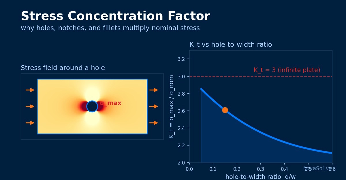
A crack in an aircraft window, a fracture starting at a bolt hole, a shaft that snaps at the shoulder where the diameter steps down. These failures share a cause that has nothing to do with the average load the part carries. The metal broke because a change in geometry concentrated stress into a tiny region, and that local peak — not the nominal stress — drove the crack.
This article explains the stress concentration factor: what it means, where the classic value of 3.0 comes from, how to apply it, and the mistakes that make engineers underestimate the danger of an innocent-looking hole.
Why this calculation matters
Real parts are not smooth bars. They have holes for fasteners, fillets where sections change, keyways, grooves, threads, and shoulders. Every one of those features disturbs the flow of stress through the material. Where the lines of force have to bend around an obstacle, they crowd together, and the local stress climbs well above the value you would compute from force divided by area.
The stress concentration factor, K_t, is the multiplier that captures this. It matters most for two failure modes. Under static loading of a brittle material, the peak stress can trigger fracture before the bulk of the section yields. Under cyclic loading, the concentrated stress is where fatigue cracks nucleate — and the vast majority of fatigue failures begin at a geometric discontinuity. If you size a part on nominal stress alone and ignore K_t, you have skipped the step where most failures are actually decided.