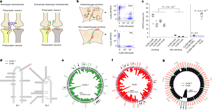
MainElectrical synapses enable the direct flow of ions and small molecules between two cells and play a prominent part in coupling electrical activity in multiple organs, including the brain2,3,4. Electrical synapses comprise multiple gap junction channels, each composed of two docked hemichannels embedded in the membranes of two touching cells. Each hemichannel is an oligomer that consists of six monomeric proteins called connexins, of which there are 21 isoforms in humans5,6. Most connexins can form single-isoform hemichannels that dock with themselves to create homotypic gap junctions (Fig. 1a, left).Fig. 1: Screen to identify a mutant connexin hemichannel pair with exclusively heterotypic docking.The alternative text for this image may have been generated using AI.Full size imagea, Left, schematic outlining the limitation of introducing heterologous WT connexin hemichannels (pink rectangles) to modulate specific neural circuits composed of neurons (brown and yellow). Note that connexin hemichannels produce off-target electrical synapses between presynaptic neurons (left). Right, strategy for using exclusively heterotypic docking hemichannels (green and red rectangles) to selectively modulate specific neural circuits. b, Depiction of red (iRFP670) and green (mEmerald) fluorescence-exchange profiles (left) and representative flow cytometry plots (right) for hemichannel pairs with (Cx36–Cx36; top) and without (Cx36–Cx45; bottom) docking compatibility. The pink dashed squares in the flow cytometry plots highlight the proportion of cells that express two distinct fluorescent proteins. c, Left, proportion of dual fluorescence-labelled cells for connexin pairs with known docking compatibility profiles. Right, FETCH scores for Cx43(F199L)–Cx43(F199L) and Cx26(K168V N176H)–Cx43 (ref. 26). Blue lines on the right-hand graph are the mean ± s.e.m. score for the known-negative distribution of connexin pairs with docking incompatibility. d, Schematic of M. americana Cx34.7 and Cx35 mutations in EL1 and EL2 used to screen for heterotypic-exclusive hemichannels. Positions and mutations specific to Cx34.7 or Cx35 or common to both proteins, are shown in green, red and black, respectively. e,f, Plots showing homotypic FETCH results for Cx34.7 (e) and Cx35 (f) mutations. The locations of these mutations can be mapped back to the structure for EL2 in d by the mutation number and colour. Circular bar graphs show the Cohen’s D effect size of FETCH scores for homotypic mutant combinations compared with the heterotypic pairing of human Cx36 and Cx45, which fails to dock. The black horizontal line in the centre is the scale bar for effect sizes. Targeted residues are listed around the circle rim; substituted amino acids are listed in the interior. The intermittent black circle segregates each targeted residue, and the light purple circle corresponds to a Cohen’s D of zero. Mutations that disrupted docking are also highlighted by black arrows and letters. g, Heterotypic FETCH results for Cx34.7 and Cx35 mutant protein combinations. Bar graphs show the effect size of heterotypic mutant combinations relative to the WT Cx34.7 and Cx35 pair. The purple circle provides the reference point for an effect size of zero. The green intermittent circle corresponds to the Cx34.7 mutations identified by green labels in the outermost level around the rim of the plot. The black horizontal line in the centre is the scale bar for effect size. For n values and statistical tests, see main text. For definitions of box plots, see Methods.Neural circuit editing using gap junctions is well established in C. elegans7,8,9,10. C. elegans do not express connexins; thus, heterologous expression of the vertebrate connexin 36 (Cx36) across two connected C. elegans neurons results in the formation of an electrical synapse that does not interact with endogenous C. elegans gap junction proteins (innexins). Previous work has successfully implemented this editing approach to modify circuit physiology in multiple behavioural contexts, including C. elegans migration in response to various chemical and temperature conditions8,9,10,11.The potential for using gap junctions to repair dysfunctional circuits has also been advanced in C. elegans, as shown in experiments that used circuit editing to restore normal behaviour in animals with induced circuit disruptions11,12. Nevertheless, this previous work highlighted a significant challenge in the use of gap junctions to edit select circuits in higher-complexity organisms. Specifically, when Cx36 was expressed in two sensory neurons of the same cell type and formed homotypic gap junctions, otherwise normal C. elegans showed disrupted behaviour in response to olfactory cues11. Because vertebrate brains are composed of many more cells of the same cell type than C. elegans, the ability of connexins to form homotypic gap junctions across more cells has the potential to substantially reduce the precision of this circuit-editing approach for mammals (for example, off-target modulation; Fig. 1a, left), which in turn produces greater behavioural disruption. Moreover, heterologous expression of connexins from other species in mammals might lead to gap junctions composed of both exogenous and endogenous connexins, thereby producing undesired connections that may impair neural circuit function.Although nearly all connexins can form homotypic channels, several connexin isoforms can dock with other connexin isoforms to generate heterotypic channels4,13 (Fig. 1a, right). We reasoned that by identifying the mechanisms that underlie the docking interactions between connexins14, we could design a hemichannel pair biased towards heterotypic gap junction formation. We also reasoned that we could engineer this pair so that it is docking-incompatible with connexins endogenous to the mammalian CNS. This strategy can therefore produce a precise approach for regulating electrical flow between distinct cell types.M. americana (white perch fish) expresses two homologues of mammalian neuronal Cx36—connexin 34.7 (Cx34.7) and connexin 35 (Cx35)—that create a heterotypic gap junction1. Notably, this electrical synapse exhibits channel-level rectification in the Cx34.7 to Cx35 direction when expressed in Xenopus oocytes1. The orthologues of Cx34.7 and Cx35 in the goldfish (Carassius auratus) CNS also create a heterotypic gap junction that shows circuit-level rectification in the same direction15. In summary, Cx34.7 and Cx35 can form heterotypic gap junctions with inherent directionality15 and can conduct currents capable of triggering action potentials1. Moreover, these connexins are potentially amenable to modification of biophysical properties through amino acid sequence mutations. On the basis of these findings, here we use Cx34.7 and Cx35 to engineer a new electrical synapse for editing mammalian circuits.In vitro assay of connexin hemichannel dockingTo establish a method for evaluating connexin docking specificity and to ultimately engineer our electrical synapse, we leveraged the natural cellular turnover of docked connexin hemichannels. In mammalian cells, connexin hemichannels can be removed from the membrane through a coordinated endocytic and exocytic process that results in the internalization of fully docked gap junctions in double-bilayer vesicles called connexosomes16,17,18,19,20,21 (Fig. 1b, top left). By fusing connexin monomers with a fluorescent protein tag, internalization of labelled gap junctions from a fluorescent cell to a non-fluorescent cell can be visualized21,22 (Fig. 1b, top).Our approach used separate populations of HEK293FT cells that were transiently transfected with individual connexins as either mEmerald or iRFP670 fluorescent fusion proteins (Fig. 1b). We then co-plated and incubated the HEK293FT cells that expressed connexin counterparts. Finally, we evaluated their fluorescence exchange by flow cytometry (Extended Data Fig. 1a–d). As hemichannel docking is a prerequisite for internalizing fluorescently tagged connexins expressed by other cells, docking can be quantified as the proportion of transfected cells that are labelled by dual fluorescence in the co-plated sample (Fig. 1b,c). We first established the utility of our assay (termed flow-enabled tracking of connexosomes in HEK293FT cells (FETCH)) by testing well-characterized connexin isoforms: Cx26, Cx36, Cx43 and Cx45. Given that each of these is capable of homotypic docking21,22,23,24, we tested them under homotypic pairings (FETCH mean ± s.e.m. = 24.8 ± 1.8%, 15.2 ± 1.1%, 19.5 ± 0.4% and 14.4 ± 0.5% dual-labelled cells for Cx26–Cx26, Cx36–Cx36, Cx43–Cx43 and Cx45–Cx45, respectively; Fig. 1c, left). We also tested them in paired combinations for which there was previous evidence13 of heterotypic docking-incompatibility (for example, Cx26–Cx43, Cx36–Cx43 and Cx36–Cx45, which had FETCH values of 2.5 ± 0.1%, 0.8 ± 0.1% and 0.9 ± 0.1%, respectively; Fig. 1c, left). Notably, the proportion of dual-labelled cells in the population of docking-compatible versus docking-incompatible pairs was significantly different (t40 = 14.5, P = 1.6 × 10⁻¹⁷, two-tailed unpaired t-test). These results establish FETCH as a method that can be used to broadly assess connexin hemichannel docking compatibility.Second, we analysed the utility of FETCH by testing two connexin mutations that affect gap junction formation. Specifically, we tested a Cx43(F199L) mutant that has previously been shown to disrupt trafficking to the cell membrane25. We also evaluated a Cx26(K168V N176H) mutant that confers heterotypic docking compatibility with wild-type (WT) Cx43 (ref. 26). In both cases, we tested whether the FETCH score for the mutants exceeded the scores for cell pairs under conditions in which docking was not anticipated (FETCH = 1.5 ± 0.2% for this ‘known negative’ distribution; n = 92 new cell pairs; Fig. 1c right, blue lines, and Methods). The homotypically paired Cx43(F199L) mutant did not exhibit a level of fluorescence exchange that was higher than the known-negative distribution (FETCH = 2.1 ± 0.3%, t96 = 0.85, P = 0.20, one-tailed unpaired t-test). By contrast, the Cx26(K168V N176H) mutant that heterotypically paired with Cx43 showed fluorescence exchange that was significantly increased (FETCH = 26.6 ± 1.3%, t96 = 30.9, P = 5.2 × 10−52, unpaired one-tailed t-test; Fig. 1c, right). Thus, we established that our FETCH assay can be used to identify connexin mutations that disrupt or enable docking compatibility.Cx34.7 and Cx35 mutant hemichannel dockingWe used FETCH to assay a library of Cx34.7 and Cx35 mutants for their impact on hemichannel docking. Although the precise interactions that guide hemichannel docking are incompletely characterized for most connexins, structure–function and sequence analyses indicate that both the extracellular loops (EL1 and EL2) play a part in hemichannel docking14,27,28,29. To identify Cx34.7 and Cx35 variants that are unable to form homotypic gap junctions, we introduced around 70 individual mutations at 16 positions on both EL1 and EL2 of each connexin (Fig. 1d, Methods (for the design of the library of mutants) and Supplementary Fig. 1). We then compared the homotypic pairing FETCH scores of the mutants to a docking-incompatible heterotypic pair30 (for example, Cx36 paired with Cx45) (Fig. 1e,f). We identified several homotypic non-docking mutant proteins for Cx34.7 (Y78S, Y78T, Y78V, E225K, E225R, L238Y and K222Q) and Cx35 (N56E, Y78V, Y78S, Y78T, E224H, E224K, E224R and L237Y) (Fig. 1e,f and Supplementary Table 1). Next, to identify mutant pairs that exhibit exclusively heterotypic docking, we tested these Cx34.7 and Cx35 mutants against each other and compared their FETCH scores to WT Cx34.7–Cx35. We discovered three connexin mutant pairs for which FETCH scores were higher than those observed for Cx34.7(WT)–Cx35(WT) gap junctions. These results provide evidence of mutant pairs (Cx34.7(K222Q) with Cx35(E224H), Cx35(E224K) or Cx35(E224R)) that have intact heterotypic but reduced homotypic docking (Fig. 1g and Supplementary Table 1).As our long-term objective was to develop a precise modulation approach that would be amenable for use in the mammalian nervous system, we also analysed whether the four identified mutant proteins could dock with the major connexins expressed by mammalian neurons and astrocytes, specifically Cx36 and Cx43, respectively31,32. For these analyses, we used FETCH and tested whether the scores for the mutant pairings were higher than that for the population of known-negative non-docking pair replicates (Methods).None of the mutant proteins interacted with human Cx43: FETCH = 1.3 ± 0.1%, t96 = 0.29, P = 0.61 for Cx34.7(K222Q)–Cx43; FETCH = 0.4 ± 0.1%, t96 = 1.41, P = 0.92 for Cx35(E224H)–Cx43; FETCH = 0.5 ± 0.1%, t96 = 1.36, P = 0.91 for Cx35(E224K)–Cx43; and FETCH = 0.5 ± 0.1%, t96 = 1.28, P = 0.90 for Cx35(E224R)–Cx43 (one-tailed unpaired t-test; n = 6 replicates for all experimental connexin pairs). Cx35(E224K) and Cx35(E224R) also did not interact with human Cx36. However, Cx34.7(K222Q) and Cx35(E224H) formed heterotypic gap junctions with human Cx36: FETCH = 22.8 ± 1.9%, t91 = −24.4, P = 3.4 × 10−43 for Cx34.7(K222Q)–Cx36; FETCH = 5.9 ± 1.1%, t96 = −5.50, P = 1.6 × 10⁻⁷ for Cx35(E224H)–Cx36; FETCH = 0.8 ± 0.1%, t96 = 0.89, P = 0.81 for Cx35(E224K)–Cx36; and FETCH = 0.6 ± 0.1%, t96 = 1.24, P = 0.89 for Cx35(E224R)–Cx36 (one-tailed unpaired t-test). Thus, although Cx35(E224K) and Cx35(E224R) both showed docking incompatibility with Cx36 and Cx43, and neither showed homotypic docking, we did not identify an effective Cx34.7 partner that did not dock with Cx36 using single-point mutagenesis.Engineering a selective Cx34.7 and Cx35 pairWe used homology modelling and FETCH analysis to design a new Cx34.7 mutant that does not dock with endogenous Cx43 or Cx36, and to design its Cx35 heterotypic docking partner. In brief, we first developed computational models of WT and mutant Cx34.7 and Cx35 hemichannels under homotypic and heterotypic pairings. We then validated the computational model by comparing the key residues predicted to underlie hemichannel docking against the docking characteristics we measured for these mutants using FETCH. We also modelled their docking interactions with Cx36. Next, we used insights from all our residue-wise interaction models to computationally design Cx34.7 and Cx35 hemichannels that would dock heterotypically only with each other. Finally, we generated these proteins and confirmed their docking characteristics in vitro using FETCH (Extended Data Fig. 1e).First, to model the docking interactions between Cx34.7 and Cx35 hemichannels, we ran molecular dynamic simulations of homotypic and heterotypic pairs of WT and mutant Cx34.7 and Cx35 proteins33,34. We found large negative interaction energies involving residues E214, K222, E223 and E225 in WT Cx34.7 and residues E213, K221, D222 and E224 in WT Cx35 for both the homotypic and heterotypic docking simulations. These large negative interaction energies were suggestive of salt bridges that stabilize both homotypic and heterotypic docking interactions. This result was consistent with our FETCH screen, in which charge-swapping mutations (that is, changing a positive charge to a neutral and a negative charge to a positive at positions Cx34.7(K222) and Cx35(E224), respectively) disrupted docking. Integrating these results, we identified a common interaction motif for both Cx34.7 and Cx35 consisting of three negative residues (E214–E213, E223–D222 and E225–E224) and a positive residue (K222–K221) (Extended Data Fig. 2a–c). This interaction motif was consistent with a previously proposed theoretical framework in which four residues underlie the docking specificity of most connexin hemichannels14.Next, we introduced Cx36 into our computational model. Both WT Cx34.7 and Cx35 showed strong interactions with Cx36, which paralleled the significant FETCH scores we observed (FETCH = 11.9 ± 1.2%, t96 = –12.93, P = 4.7 × 10⁻²³ for Cx34.7–Cx36; FETCH = 18.0 ± 2.0%, t96 = –18.69, P = 4.7 × 10⁻³⁴ for Cx35–Cx36, compared against the known-negative distribution, one-tailed unpaired t-test). We then modelled the four non-docking connexin mutants identified in our initial FETCH analysis (Cx34.7(K222Q), Cx35(E224H), Cx35(E224K) and Cx35(E224R)) against Cx36. Although the K222Q variant disrupted the large negative interaction energies we observed in the homotypic WT Cx34.7 model, the three remaining negative residues in the motif that contribute to docking compatibility in Cx34.7(K222Q) continued to show large negative interaction energies with the positive central lysine residue of Cx36. This result provides a potential mechanism for the heterotypic docking between Cx34.7(K222Q) and CX36 we observed via FETCH. By contrast, the three candidate Cx35 mutants we tested against Cx36 using FETCH (Cx35(E224H), Cx35(E224K) and Cx35(E224R)) maintained the positive K221 residue that formed strong interactions with the negative residues of Cx36. However, the Cx35(E224K) and Cx35(E224R) mutants induced strong repulsion with the positive K238 residue of Cx36. This finding provides insight into why these two mutants do not heterotypically dock with Cx36 in our FETCH analyses. Moreover, introducing a neutrally charged residue at the E224 position, as observed in the Cx35(E224H) mutant, was sufficient to restore the interaction with Cx36 in the computational model, which again mirrored the heterotypic docking profile we observed from our FETCH analyses.Having modelled the putative interaction principles that underlie the docking specificity between Cx34.7, Cx35 and Cx36 and validated our models using FETCH, we set out to design a Cx34.7–Cx35 pair that would exhibit heterotypic docking only with each other. Our strategy was to mutate residues at the four positions of our identified docking motif such that one connexin isoform contained all negatively charged interactors (Cx35) and the other all positive (Cx34.7). Our Cx35 mutant Cx35(K221E) showed strong repulsions in our homotypic model (Extended Data Fig. 2e), did not exhibit homotypic docking, on the basis of FETCH analyses (FETCH = 1.2 ± 0.4%, t96 = 0.35, P = 0.64, one-tailed unpaired t-test) and did not dock with Cx36 or Cx43 (FETCH = 1.5 ± 0.1%, t91 = 0.02, P = 0.51 for Cx35(K221E)–Cx36; FETCH = 1.7 ± 0.2, t96 = –0.32, P = 0.37 for Cx35(K221E)–Cx43, one-tailed unpaired t-test). Similarly, the positively charged motif mutant Cx34.7(E214K E223K E225K) showed strong repulsions in our homotypic computational model and did not exhibit homotypic docking in FETCH analyses (FETCH = 0.2 ± 0.0%, t96 = 1.76, P = 0.96, one-tailed unpaired t-test). However, when we assayed Cx35(K221E) against Cx34.7(E214K E223K E225K) using FETCH, we did not observe significant fluorescence exchange (FETCH = 1.2 ± 0.3%, t96 = 0.37, P = 0.64, one-tailed unpaired t-test). Follow-up confocal imaging analyses of HEK293FT cells expressing the constructs revealed that Cx34.7(E214K E223K E225K) did not properly localize to the cell membrane (compare Extended Data Fig. 2g and Extended Data Fig. 2h; see also Extended Data Fig. 3). Moreover Cx34.7(E214K E223K E225K) was predicted to show weak attractive interactions with Cx35(K221E) in our heterotypic gap junction computational model (Extended Data Fig. 3). Thus, we evaluated an intermediate Cx34.7 mutant protein that exhibited positively charged residues at three out of the four critical interacting positions, Cx34.7(E214K E223K). This mutant showed repulsive interactions in our homotypic gap junction computational model (Extended Data Fig. 2d), and it showed strong attractive interactions with Cx35(K221E) (Extended Data Fig. 2f). This mutant docked with Cx35(K221E) as confirmed via FETCH analysis and confocal microscopy (FETCH = 35.7 ± 4.1%, t96 = 28.11, P = 2.0 × 10−48, one-tailed unpaired t-test; Extended Data Fig. 2i). Notably, Cx34.7(E214K E223K) did not show homotypic docking in our FETCH analysis (FETCH = 1.1 ± 0.2%, t96 = 0.46, P = 0.68, one-tailed unpaired t-test), nor did it dock with Cx36 or Cx43 (FETCH = 1.0 ± 0.2%, t96 = 0.58, P = 0.72 for Cx34.7(E214K E223K)–Cx36; FETCH = 0.9 ± 0.1%, t96 = 0.73, P = 0.77 for Cx34.7(E214K E223K)–Cx43, one-tailed unpaired t-test). Notably, the Cx34.7(E214K E223K) and Cx35(K221E) mutant pair showed a higher heterotypic FETCH score than CX36 under homotypic docking conditions (FETCH = 15.2 ± 1.1%) and the WT Cx34.7–Cx35 pair (FETCH = 12.0 ± 0.9%) as measured using our in vitro assay (t10 = 4.9, P = 6.4 × 10⁻⁴ for comparisons against Cx36–Cx36; t10 = 5.7, P = 1.9 × 10⁻⁴ for comparisons against WT Cx34.7–Cx35, two-tailed unpaired t-test at an α threshold adjusted by false discovery rate (FDR) correction for 2 comparisons; n = 6 replicates per group). From hereon, we refer to this connexin pair of Cx34.7(E214K E223K) and Cx35(K221E) as Cx34.7(M1)–Cx35(M1); that is, designer connexin version 1.0 from M. americana.Cx34.7(M1) and Cx35(M1) form a functional synapseTo determine whether our mutant Cx34.7 and Cx35 hemichannels can form a functional electrical synapse, we used Xenopus oocytes as a heterologous expression system35,36. We also tested WT Cx34.7 and Cx35 hemichannels as controls. Connexins were expressed in separate populations of oocytes. Oocytes expressing either two different connexins or the same connexin were then paired to form heterotypic or homotypic gap junctions, respectively (Fig. 2a and Methods). In our analyses of heterotypic gap junctions, we detected junctional current (Ij) in paired oocytes expressing Cx34.7(M1) and Cx35(M1) (Fig. 2b, bottom). As expected, we also detected current in pairs expressing the WT proteins (Fig. 2b, top). In response to symmetric transjunctional voltage (Vj) steps (–120 mV to +120 mV), the mutant heterotypic gap junction exhibited significantly lower instantaneous Ij (Ij,inst) and steady-state Ij (Ij,ss) currents than the WT heterotypic gap junction (unpaired two tailed t-test, n = 6 per group; Fig. 2c). The Ij traces for mutant and WT pairs seemed to be asymmetric between the positive and negative Vj ranges, and the Ij traces recorded from one oocyte in a pair looked like a mirror image of those recorded from the other oocyte of the pair (Fig. 2b). As these findings were indicative of a rectification property of the mutant and WT gap junctions, we normalized the Ij,inst and Ij,ss and compared the rectification index (Fig. 2d,e). The Ij,ss was rectified in the Cx34.7 to Cx35 direction for the mutant and WT pairs, a result consistent with a report for the WT proteins1. By contrast, Ij,inst was rectified in the opposite direction for both pairs (unpaired two tailed t-test, n = 6 per group; Fig. 2e).Fig. 2: Biophysical properties of gap junctions formed by heterologous expression of WT and mutant Cx34.7 and Cx35 in Xenopus oocytes.The alternative text for this image may have been generated using AI.Full size imagea, Diagram showing the characterization of connexin gap junctions using oocyte pairs. The membrane voltage (Vm) of oocyte 1 was stepped from a holding voltage of –30 mV to a series of voltages (−150 mV to +90 mV at 10-mV intervals), whereas that of oocyte 2 was held constant at −30 mV to record junctional currents (Ij). b, Representative Ij traces from oocyte pairs expressing WT (Cx34.7(WT)–Cx35(WT), top) or mutant (Cx34.7(M1)–Cx35(M1), bottom) connexins. c, Relationships between instantaneous Ij (Ij,inst) and transjunctional voltage (Vj) (left), and between steady-state Ij (Ij,ss) and Vj (right). Vj is defined as Vm of oocyte 2 – Vm of oocyte 1. d, Relationships between normalized Ij,inst and Vj, and between normalized Ij,ss and Vj. Ij was normalized to the peak current value of the side with the lower absolute magnitude. e, Comparison of Ij,inst and Ij,ss rectification indices. The rectification index is the ratio of the peak Ij recorded from the indicated side (for example, Cx34.7(WT) side or Cx35(WT) side) to the peak Ij from the opposing side. WT (Cx34.7(WT)–Cx35(WT)) and mutant (Cx34.7(M1)–Cx35(M1)) heterotypic gap junctions did not show significant differences in the rectification index. f, Representative Ij traces of homotypic gap junctions formed by Cx34.7(WT), Cx34.7(M1), Cx35(WT) and Cx35(M1). g, Relationships between Ij,inst and Vj, and between Ij,ss and Vj (n = 12 cell pairs per group). h, Comparison of the maximal Ij,inst and Ij,ss at positive and negative Vj among the different gap junctions. Bar graphs show the mean ± s.e.m. i, Schematic of the experimental setup for the functional characterization of connexin pairs. j, A representative HEK293FT cell pair from data presented in l. Scale bar, 10 μm. k, Schematic of recording for a Cx34.7(M1)–Cx35(M1) cell pair. Voltage steps (−160 mV to +70 mV at 10-mV intervals from a holding voltage of −45 mV) were applied to one cell (top), and the resulting Ij traces were recorded from the neighbouring cell (bottom) at an expanded time scale (only half of the voltage steps are depicted). l, Current at the maximum Vj for WT and connexin double-knockout HEK293FT cells and for double-knockout cell pairs transfected with Cx36, Cx34.7(M1) or Cx35(M1) under conditions of homotypic and heterotypic pairing. The number of cell pairs recorded is shown above individual boxes. For n values and statistical tests, see the main text. For definitions of box plots, see Methods.In our analyses of homotypic gap junctions, we detected Ij from oocytes expressing Cx34.7(WT), Cx35(WT) and Cx34.7(M1) but not Cx35(M1) (n = 12 per group; Fig. 2f). The homotypic gap junctions differed in Ij amplitude (unpaired two-tailed t-test; Fig. 2g,h), the relationship between the steady-state junctional conductance (Gss) and the Vj and the deactivation rate (Extended Data Fig. 4). Overall, these findings confirmed the formation of functional Cx34.7(M1)–Cx35(M1) gap junctions and the disruption of Cx35(M1) homotypic docking. These observations were consistent with our initial screening analysis using FETCH. Contradictory results were observed for Cx34.7(M1) under homotypic conditions, whereby we observed functional gap junctions using Xenopus oocytes but disrupted docking using FETCH in mammalian cells.To address these conflicting findings observed for Cx34.7(M1) under homotypic conditions, we next tested whether Cx34.7(M1) can form a functional homotypic electrical synapse in HEK293FT cells and thereby increase their electrical coupling (experimental setup for the functional characterization of connexin hemichannel pairs in HEK293FT cells is shown in Fig. 2i). Here we used CRISPR–Cas9 to generate a new HEK293FT cell line for which expression of the endogenous Cx43 and Cx45 proteins was disrupted (connexin double-knockout HEK293FT cells; Methods and Extended Data Fig. 5). This approach reduces the number of electrical synapses that naturally form between HEK293FT cells37 (Fig. 2l, left), which enabled us to assess whether functional connectivity is increased by Cx34.7(M1) expression. Heterotypic expression of Cx34.7(M1) and Cx35(M1) increased electrical connectivity between pairs of connexin double-knockout HEK293FT cells (H4,48 = 17.45, P = 0.0016, Kruskal–Wallis test; U = 60 and P = 0.007 compared with non-transfected connexin double-knockout cell pairs for post hoc analysis, one-tailed Wilcoxon rank-sum test at an α threshold adjusted by FDR for 4 comparisons; Fig. 2j–l and Extended Data Fig. 6). By contrast, neither homotypic expression of Cx34.7(M1) nor Cx35(M1) increased connectivity (U = 95 and P = 0.67 for Cx34.7(M1), and U = 87 and P = 0.42 for Cx35(M1) for post hoc comparisons with non-transfected connexin double-knockout cells, one-tailed Wilcoxon rank-sum test at an α threshold adjusted by FDR for 4 comparisons; Fig. 2l). Thus, in addition to finding that Cx34.7(M1) does not dock in a homotypic configuration in our FETCH analysis, Cx34.7(M1) does not form a functional homotypic electrical synapse when expressed in a mammalian cell line.Cx34.7(M1)–Cx35(M1) alters function and behaviourNext, we set out to determine the in vivo docking selectivity and functionality of our Cx34.7(M1) and Cx35(M1) hemichannels by testing whether distinct hemichannel pairs can regulate the activity of two neurons that constitute a circuit and their output behaviour. Specifically, we evaluated hemichannels under homotypic and heterotypic conditions against the other major connexin proteins expressed in the mammalian CNS (Cx36 and Cx43). We anticipated that these experiments would further clarify whether the inconsistent homotypic interaction observed for Cx34.7(M1) hemichannels between our Xenopus oocyte and HEK293FT FETCH experiments could potentially limit their application for precision circuit editing in mammals. We also tested our Cx34.7(M1) and Cx35(M1) channels under heterotypic conditions to confirm their in vivo functionality.Here we capitalized on C. elegans as a model for testing, as multiple groups have established that selectively expressing Cx36 is sufficient to reconstitute a functional electrical synapse between two connected neurons. The presence and function of this Cx36–Cx36 synapse has been confirmed through microscopy8, measurements of synaptic physiology8, calcium imaging10 and behaviour7,8,9,10,11,12. Thus, we assessed whether we could induce changes in calcium imaging and behaviour with Cx34.7(M1)–Cx35(M1) in a manner that mirrored Cx36–Cx36.C. elegans do not have an innate temperature preference and can thrive in a broad range of temperatures38. However, C. elegans trained at a particular temperature in the presence of food will migrate towards that temperature when they are subsequently placed on a temperature gradient38. This learned preference is in part mediated by plasticity of the synapse between a thermosensory neuron (AFD, presynaptic) and an interneuron (AIY, postsynaptic)39. Notably, plasticity in AFD can be genetically manipulated to affect transmission to AIY and to predictably encode the behavioural preference that must otherwise be learned10.We have previously shown that heterologous expression of Cx36 can be used to edit this circuit by bypassing the presynaptic plasticity mechanisms between AFD and AIY that contribute to the learned temperature preference10. Thus, circuit-edited worms show a persistent preference for warmer temperatures (Fig. 3a). We therefore used this circuit to validate the functionality of our engineered gap junction proteins (as assessed by calcium imaging and quantitative behaviour testing).Fig. 3: Heterologous connexin hemichannels couple C. elegans neurons and recode thermal preference.The alternative text for this image may have been generated using AI.Full size imagea, Schematic of AFD→AIY synaptic communication and expressed temperature preference. The AFD thermosensory neuron has a robust calcium response to warming stimuli. C. elegans raised in the presence of food at 15 °C, or animals with a gain-of-function mutation in the gene encoding protein kinase-C1 (caPKC-1 GOF), move towards cooler temperatures when placed on a thermal gradient from 18 to 22 °C (top). Heterologous expression of Cx36 hemichannels between AFD and AIY synchronizes AIY and promotes warm-seeking behaviour (bottom). b, Left, calcium traces of neurons expressing heterologous connexin hemichannel pairs, along with baseline AFD and AIY responses. Each panel depicts the average group trace (top, mean ± s.e.m.), heatmaps of individual animals (middle) and the temperature stimulus (bottom). ΔF/F values in heatmaps are presented as percentages (for example, a value of 0.2 for ΔF/F is 20%). Right, behavioural traces for WT C. elegans (N2) and C. elegans homotypically expressing WT connexin hemichannels, homotypically expressing mutant connexin hemichannels or heterotypically expressing the mutant pair. c, Proportion of animals showing neuronal calcium responses based on the traces in b. ***P < 0.0005, two-tailed Fisher’s exact test for penetrance; error bars denote 95% confidence interval (CI). n = 61, 65, 55, 46, 50, 53, 49 and 46 animals (left to right). d, Thermotaxis preference (TTX) indices for experimental groups. olaIs17, control (expresses GCaMP and fluorophore without connexin hemichannel expression). Each individual point represents the TTX index of a separate assay. n = 30, 6, 6, 6, 6, 6 and 6 assays for the groups shown (left to right), N = 12–15 animals per assay. The black horizontal line depicts the median for each group. **P < 0.005, ***P < 0.0005 versus N2, two-tailed Dunnett’s T3 multiple comparisons test; error bars denote 95% CI. NS, not significant.We first expressed Cx34.7(M1) in AFD cells and expressed Cx35(M1) in AIY cells (Extended Data Fig. 7a and Supplementary Table 2). Similar to Cx36–Cx36, expression of Cx34.7(M1)–Cx35(M1) in the AFD–AIY pair resulted in functional coupling between AFD and AIY, as assessed by calcium imaging (Fig. 3b, left, and 3c; P < 0.0005, two-tailed Fisher’s exact test with FDR correction). The C. elegans constitutively migrated towards warmer temperatures when placed on a thermal gradient, which mirrored the behaviour of animals expressing heterologous Cx36–Cx36 (F7,17.91 = 84.99, P < 0.0001, Welch one-way analysis of variance (ANOVA) followed by Dunnett’s T3 multiple comparisons; P < 0.005 versus WT N2 animals; Fig. 3b, right, and 3d). Homotypic expression of Cx34.7(WT) or Cx35(WT), but not Cx34.7(M1) or Cx35(M1), in both AFD and AIY neurons synchronized the two cells and modulated behaviour (Fig. 3b–d; P < 0.0005 versus WT N2 animals). We also evaluated Cx34.7(M1) and Cx35(M1) hemichannels against Cx36 and CX43. C. elegans expressing Cx34.7(M1)–Cx36, Cx34.7(M1)–Cx43, Cx36–Cx35(M1) or Cx43–Cx35(M1) in AFD–AIY pairs all continued to migrate towards cold temperatures (F7,10.67 = 19.29, P < 0.0001, Welch one-way ANOVA followed by Dunnett’s T3 multiple comparisons; P > 0.05 for all comparisons against N2 animals; Extended Data Fig. 7b).Taken together, these findings confirmed that our Cx34.7(M1)–Cx35(M1) electrical synapse modified C. elegans behaviour and physiology in a manner that was statistically indistinguishable from the Cx36–Cx36 electrical synapse. Our findings also supported the docking properties we predicted for the mutants using our in vitro screen and in silico studies. That is, both Cx34.7(M1) and Cx35(M1) did not alter behaviour and physiology when expressed in homotypic configurations or in heterotypic configurations against Cx36 and Cx43.Cx34.7(M1)–Cx35(M1) enhances circuit synchrony in miceHaving established the in vivo docking selectivity and functionality of our Cx34.7(M1)–Cx35(M1) pair, we set out to determine whether these proteins can modulate mesoscale neural circuitry in mammals. After verifying their expression and trafficking (Extended Data Fig. 8a), we chose to edit a circuit composed of two distinct cell types. Mice are an ideal species in which to test cell-type specificity because they are highly amenable to cell-type-specific access via selective promoters and Cre-recombinase targeting. Excitatory pyramidal neurons (PYR) and parvalbumin-expressing fast-spiking (PV+) interneurons can form microcircuits whereby PYR neurons excite PV+ interneurons, which in turn inhibit PYR neurons (Fig. 4a). This PYR–PV+ interneuron microcircuit has been well characterized in the hippocampus. In detail, medial prefrontal PYR neurons show activity coupled to the phase of hippocampal theta frequency oscillations (4–10 Hz) during spatial exploration40, whereas PV+ interneuron activity is coupled to hippocampal gamma frequency oscillations (30–80 Hz)41. Notably, the activity of this PYR–PV+ interneuron microcircuit is reflected in the synchrony between the phase of theta oscillations and the amplitude of gamma oscillations in rodents42.Fig. 4: LinCx edits microcircuit dynamics at the millisecond timescale in mice.The alternative text for this image may have been generated using AI.Full size imagea, Schematic of a prefrontal cortex microcircuit comprising a PYR neuron and PV+ interneurons. The tan circle highlights the target for LinCx editing. b, PV-Cre mice were injected with AAV-CaMKII-Cx34.7(M1) (green) and AAV-DIO-Cx35(M1) (red) into the prelimbic cortex (PrL) and subsequently implanted with microwires. Control mice were injected with a Cx34.7(M1) or Cx35(M1) pair of viruses to express the same hemichannel in both cell types. c, Representative LFPs recorded from the PrL (top row). Power spectrograms show theta and HFO activity, corresponding to PYR neuron and PV+ interneuron firing, respectively (middle row). Microcircuit function is represented by the coupling between the phase of theta oscillations (black) and the amplitude of HFOs (red) (bottom row). d, Distribution of theta–HFO coupling scores (modulation index) observed across non-injected C57BL/6J mice, PV-Cre mice injected with a Cx34.7(M1) or Cx35(M1) pair of viruses or mice injected with a docking Cx34.7(M1)–Cx35(M1) pair. e, Mice with the Cx34.7(M1)–Cx35(M1) pair showed higher theta–HFO coupling (left), but not theta or HFO power (middle, right), than mice expressing Cx34.7(M1) and Cx35(M1) under homotypic conditions (same mice as shown in Fig. 5d). f, Circuit editing had no significant impact on theta–low gamma oscillatory coupling (left) or low gamma power (right) for these mice (same mice as shown in Fig. 5d). g, PV-Cre mice were bilaterally injected with AAV-CaMKII-Cx34.7(M1) and AAV-DIO-Cx35(M1) (left). Control mice were injected with AAV-CaMKII-eGFP and AAV-DIO-mCherry (middle). Mice were subsequently implanted with silicon probes (right). h, Waveform properties of PV+ interneurons recorded from Cx34.7(M1)–Cx35(M1) and eGFP-mCherry (control) mice (P = 0.29 for peak valley ratio; P = 0.88 for half-width). Inset in left-hand graph shows the mean firing rate of PV+ interneurons. i, Left, activity of PV+ interneuron and theta oscillations recorded concurrently from the same channel (top). Theta oscillation phase firing distributions of a PV+ interneuron recorded from an experimental mouse (middle) and a control mouse (bottom). Right, distribution of MRLs across the population of PV+ interneurons recorded from experimental and control mice (top). Distribution of Rayleigh test statistics across the same populations of PV+ interneurons (bottom), in which Z = –log [P]. Insets show the same data as a box and whisker plot. Same neurons as shown in h. j, Waveform properties of PYR excitatory neurons recorded from Cx34.7(M1)–Cx35(M1) and control mice. Inset shows the mean firing rate of PYR neurons, which was lower in LinCx-edited mice. k, Raster plot showing a PYR neuron and two PV+ interneurons that were recorded concurrently. l, Cross-correlation between the PYR neuron and two PV+ interneurons shown in k, determined at temporal shifts up to ±5 s between the spike trains. The horizontal line in each plot is the maximum cross-correlation in the 1–4-ms window. For the PV+ interneuron in blue, the maximum cross-correlation in 1–4 ms exceeds more than 98.75% of the values determined at temporal shifts ranging from ±3–5 s (corresponding to α = 0.05/4 for the 1–4-ms window), whereas the maximum cross-correlation did not exceed this threshold for the red PV+ interneuron. Thus, only the blue PV+ interneuron neuron shows coupling to the PYR. m, A higher proportion of PYR–PV+ pairs with significant short-latency coupling was found in the LinCx-edited mice (right) relative to the control mice (left). n, Left, schematic of the social-preference test to assess the impact of PYR–PV+ interneuron microcircuit editing on social behaviour. Right, LinCx-edited mice exhibited an increase in social preference relative to control mice. o, LinCx-edited mice exhibited higher exploratory drive in a novel environment compared with controls (left, middle). No group difference in gross locomotor behaviour was observed following habituation. Same mice as shown in n. For n values and statistical tests, see main text. For definitions of box plots, see Methods. Brain slice images in b and g were adapted from ref. 55.PYR–PV+ interneuron microcircuits are also observed in the prefrontal cortex, but with slightly different neurophysiological properties43. As observed in the hippocampus, prefrontal cortex PYR neurons phase-couple to locally recorded theta oscillations44. Conversely, prefrontal PV+ interneurons best couple to the phase and amplitude of local high-frequency oscillations (HFOs, 80 ≠ 200 Hz)45. Thus, to determine the effect of our electrical synapse, we quantified the coupling between the phase of prefrontal cortex theta oscillations and the amplitude of prefrontal cortex HFOs as a proxy for prefrontal PYR–PV+ interneuron microcircuit activity. Specifically, we expressed our Cx34.7(M1)–Cx35(M1) synapse at the PYR–PV+ interneuron interface. We proposed that this manipulation would enhance the coupling between theta oscillations and HFOs in the prefrontal cortex.We developed an AAV virus (AAV9-Ef1α-DIO-Cx35(M1)) to selectively target Cx35(M1) to cells expressing Cre-recombinase and another virus (AAV9-CaMKII-Cx34.7(M1)) to express Cx34.7(M1) nonselectively across all neurons. We then injected PV-Cre mice with both viruses bilaterally in the prelimbic cortex (n = 11; Fig. 4b). A group of PV-Cre control mice was injected with viruses to only express Cx34.7(M1) or Cx35(M1) nonselectively across all neurons (n = 7 per connexin; Methods and Extended Data Fig. 8b). Finally, we also tested a third group of control C57BL/6J mice that had not been injected with virus (n = 29). Neural oscillatory activity was recorded from the prelimbic cortex while mice explored an open field.To determine the coupling between theta oscillations (4–10 Hz) and HFOs (80–200 Hz), we isolated local field potential (LFP) activity in these two frequency bands (Fig. 4c). We then determined their phase–amplitude coupling relationships using the established modulation index (z score), which quantifies the statistical likelihood that measured relationships between two oscillations would be observed by chance46 (Methods). We found significant theta–HFO coupling from the majority of implanted mice (80%, 43 out of 54; Fig. 4d). We then tested whether coupling was higher in mice expressing our electrical synapse than in controls, a result that signified an increase in electrical coupling. Indeed, theta–HFO coupling was significantly higher in the LinCx-expressing mice than in the pooled group of control mice expressing the connexins under homotypic configurations (U = 141, P < 0.013, one-tailed rank-sum test, Cohen’s D = 0.99; Fig. 4e). Thus, expression of the synapse was sufficient to enhance coupling in a microcircuit defined by two precise cell types in mammals. Notably, our post hoc analysis did not show differences in theta–HFO coupling between mice expressing homotypic Cx34.7(M1)–Cx34.7(M1) or Cx35(M1)–Cx35(M1) synapses compared with uninfected C57BL/6J control mice (U = 509 and P = 0.28 for Cx34.7(M1)–Cx34.7(M1), U = 542 and P = 0.84 for Cx35(M1)–Cx35(M1), two-tailed rank-sum test). These findings support the heterotypic selectivity of the two mutant proteins in vivo.In our secondary analyses, there were no differences in theta or HFO power between mice expressing the synapse and the control mice expressing mutant connexins in homotypic configurations across the PYR–PV+ interneuron microcircuit (U = 172 and P = 0.60 for theta power, U = 167 and P = 0.43 for HFO power, two-tailed rank-sum test; Fig. 4e). Similarly, no group differences in theta–low gamma oscillation cross-frequency phase coupling (U = 176 and P = 0.76, two-tailed rank-sum test; Fig. 4f) or low gamma oscillation power (U = 161 and P = 0.26, two-tailed rank-sum test) were observed (Fig. 4f). Thus, our electrical synapse selectively increased the synchrony between theta and HFO activity in the medial prefrontal cortex.Next, we tested whether this increased synchrony could be observed at the level of single neurons. Three new experimental PV-Cre mice were infected with AAV9-hsyn-DIO-Cx35(M1)-T2A-mCherry to selectively target Cx35(M1) to cells expressing Cre-recombinase and with the nonselective AAV9-CaMKII-Cx34.7(M1)-mEmerald virus. Three control mice were infected with AAV9-hsyn-DIO-mCherry and AAV9-CaMKII-eGFP. Two weeks later, these mice were implanted with high-density silicon recording probes (Fig. 4g and Extended Data Fig. 8c). Following recovery, neural activity was recorded for 10 min while mice were in their home cage. PV+ interneurons were identified on the basis of previously validated waveform criteria (for example, a peak to valley ratio of <1.1 and a mean firing rate of >10 Hz)47. No group differences in waveform properties were observed (t190 = 1.07 and P = 0.29 for peak valley ratio, t190 = 0.15 and P = 0.88 for half-width, unpaired two-tailed t-tests; n = 91 and 101 total medial prefrontal cortex PV+ interneurons for the experimental and control groups, respectively; Fig. 4h).After establishing that the activity of prefrontal cortex PV+ interneurons was better coupled to the phase of HFOs than gamma oscillations (Extended Data Fig. 9), we compared the activity profiles of PV+ interneurons across the two groups. We did not observe group differences in the mean firing rate of PV+ single units (t190 = 0.90 and P = 0.37 for comparisons of firing rate, unpaired two-tailed t-test; Fig. 4h). This result was consistent with our finding that the electrical synapse did not affect the amplitude of HFO activity in the prefrontal cortex (Fig. 4e, right). Next, we quantified the coupling of activity for each PV+ interneuron to local theta oscillations by determining its mean resultant length (MRL) and with the Rayleigh test of circular uniformity (Fig. 4i). In contrast to a previous study45, most PV+ interneurons showed phase coupling to theta oscillations in both groups (69 out of 91 and 83 out 101 neurons for experimental and control mice, respectively). As proposed, the experimental mice showed stronger PV+ phase coupling to theta oscillations than the control group (t190 = 2.34 and P = 0.01 for MRL, t190 = 2.31 and P = 0.01 for Rayleigh Z, unpaired one-tailed t-tests, Cohen’s D = 0.33; Fig. 4i). Thus, the engineered electrical synapse increased the coupling of PV+ interneurons to theta oscillations, again consistent with our observations for the coupling of HFO activity.Next, we directly quantified coupling between cells in the PYR–PV+ interneuron microcircuit. We isolated 128 and 79 putative PYR neurons from experimental mice and control mice, respectively (Fig. 4j), on the basis of previous criteria (for example, a spike half-width of >250 µs and a mean firing rate of <20 Hz)48. Incidentally, we observed a reduced PYR neuron firing rate in the LinCx-edited mice (t205 = 5.56 and P = 8.58 × 10⁻⁸, two-tailed unpaired t-test; Fig. 4j, inset). We then performed cross-correlation analysis between 5,616 pairs of concurrently recorded PYR neurons and PV+ interneurons (Fig. 4k) and used permutation testing to determine whether each pair was significantly coupled with short latency (1–4 ms; Fig. 4k,l, Methods and Supplementary Fig. 2). We found that 312 out of 2,801 PYR–PV+ pairs (11%) were significantly coupled in the control mice. A higher proportion of PYR–PV+ pairs (17%) were significantly coupled in the LinCx-edited mice (468 out of 2,815 pairs; χ2 = 35, P < 0.0001, chi-square test, Φ = 0.08; Fig. 4m). Together, these data demonstrate that our electrical synapse selectively increases millisecond timescale coupling in the PYR–PV+ interneuron circuit in the medial prefrontal cortex.Finally, increased prefrontal cortical excitability and microcircuit dysfunction have been implicated in mediating social deficits in autism. As LinCx editing decreased prefrontal cortex excitability and increased microcircuit coupling, we tested whether this manipulation would enhance social behaviour. LinCx-edited mice exhibited a higher preference for the social stimulus in a social preference task (t13 = 2.55 and P = 0.012 for LinCx-edited versus control mice, unpaired one-tailed t-test, n = 7–8 per group, Cohen’s D = 1.1; Fig. 4n). Notably, LinCx-edited mice also exhibited increased exploratory drive when placed in a novel open-field (t13 = 2.69 and P = 0.018 for LinCx-edited versus control mice, two-tailed unpaired t-test; Fig. 4o, left and middle). No differences in gross locomotor behaviour were observed when animals were previously habituated to the testing arena (t13 = 0.37 and P = 0.72 for LinCx-edited versus control mice, two-tailed unpaired t-test; Fig. 4o, right). Overall, these findings show that expression of the LinCx electrical synapse causally enhances coupling of single-unit activity in a local mammalian cortical microcircuit and modifies behaviour accordingly.Cx34.7(M1)–Cx35(M1) potentiates a long-range circuitWe next tested whether our electrical synapse could potentiate a long-range circuit consisting of cells in two different brain regions. The infralimbic cortex (IL, an anatomical subdivision of the mouse medial prefrontal cortex) sends a monosynaptic projection to medial dorsal thalamus (MD) in mice. We selected this circuit to test the functionality of Cx34.7(M1)–Cx35(M1) given our previous experience in quantifying its physiological properties and role in stress behaviour49,50. Specifically, the tail-suspension test is a classical assay that measures the behavioural response of mice to an inescapable negative experience in which they are suspended upside down by their tail51. Exposure to stress reduces behavioural responses during the assay52, and the assay induces a robust stress response53. Thus, repeated exposure to the tail-suspension test increases immobility during subsequent testing50 (Fig. 5a, top). This behavioural adaptation is specific to the stress context, as decreased mobility is not observed when locomotor behaviour is quantified in an open field immediately before each tail-suspension stress session50.Fig. 5: LinCx edits a long-range circuit in mice.The alternative text for this image may have been generated using AI.Full size imagea, Behavioural and neurophysiological impacts of repeated tail-suspension stress (data from ref. 50). Bottom, increased coupling between IL 2–7 Hz oscillations and MD 30–70 Hz oscillations due to repeat tail-suspension test exposure. b, Top row, schematic of the closed-loop optogenetic approach to synchronizing MD firing to IL oscillations as performed in our previous work50. Second row, behavioural impact of causally coupling MD activity to IL 2–7 Hz oscillations using closed-loop optogenetic stimulation. Middle and bottom rows, behavioural outcomes of stimulating MD (middle) or IL terminals (bottom) in the MD with a pattern uncoupled to ongoing IL activity (open-loop optogenetic stimulation). c, Viral and optical fibre or electrode targeting approach (top), and experimental timeline for optogenetic interrogation of the IL→MD circuit (bottom). d, Representative plots showing coupling between IL and MD oscillations for Cx34.7(M1)–GFP control mice (top left) and Cx34.7(M1)–Cx35(M1) mice (top right). Mice injected with the Cx34.7(M1)–Cx35(M1) pair showed higher coupling between IL 2–7 Hz and MD 30–70 Hz oscillations (bottom left), but there were no group differences in IL 2–7 Hz or MD 30–70 Hz oscillatory power (bottom right; data shown as the mean ± s.e.m.; note that the distributions overlap). e, Representative LFP oscillations from the MD in response to an optogenetic light pulse in the IL (light blue vertical line). LFP activity was averaged across 120 light pulses (1 mW, 10 ms pulse width) to produce the MD-evoked potential in red. f, MD neuronal response to an optogenetic light pulse in the IL (light blue vertical line). Data shown for MD unit M1P1-135. Cellular activity across 120 light pulses is shown below, with the evoked potential recorded from the same channel overlaid in red. The positive deflection in the evoked potential reflects firing of the neuron. g, Top, representative LFP oscillations recorded from the IL and MD during light stimulation. Note the four highlighted supraphysiological IL responses induced by light stimulation (light blue arrows). Representative mean light-evoked potential recorded concurrently from an MD (middle) and IL microwire (bottom). Note the large negative instantaneous deflection in the IL channel and the positive deflection the MD channel (black arrows). Data shown as the mean ± s.d. across about 30 light pulses. h, Changes in amplitude of evoked potential across sessions in the MD (top) and IL (bottom) in mice expressing Cx34.7(M1)–Cx35(M1) versus control mice. Same mice as shown in d. i, Viral injection strategy and experimental timeline for quantifying the impact of IL→MD LinCx editing on behaviour. j, Immobility time during repeat tail suspension (left) and distance travelled during repeat open-field testing (right). A pooled group of mice injected with Cx34.7(M1) or Cx35(M1) in homotypic non-docking configurations showed stress-induced behavioural adaptation during repeat tail-suspension testing, whereas mice injected with the functional Cx34.7(M1)–Cx35(M1) pair did not. No behavioural differences were observed between viral groups in the open-field test (^group effect; *group × day interaction effect, mixed-effects model ANOVA). Bars reflect group means. k, Summary of biophysical and electrophysiological properties of Cx34.7(M1) and Cx35(M1). DKO, double knockout; NA, not applicable. For n values and statistical tests, see the main text. For definitions of box plots, see Methods. Brain slice images in c and i were adapted from ref. 55.In our previous work, we found that exposure to the tail-suspension test induced coupling between low-frequency oscillations in the IL and low gamma oscillations in the MD50 (Fig. 5a). Furthermore, when we exogenously recapitulated coupling between the IL and MD using a brain–machine interface, mice showed reduced behavioural adaptation in the assay50. Stimulation of the MD in a manner that was uncoupled to IL activity did not produce this outcome50 (see Fig. 5b for a summary). Together, these findings established the role of the IL→MD circuit in stress compensatory behaviour50.In the current study, we injected BALB/cJ mice with AAV9-CaMKII-Cx34.7(M1) and AAV9-CaMKII-ChR2 in the left IL. Three weeks later, we injected these mice with AAV9-CaMKII-Cx35(M1) in the left MD and implanted microwire recording electrodes in the IL and MD (Fig. 5c). After another 5 days of surgical recovery, we recorded baseline LFP activity and activity in response to 10-ms pulses of optogenetic stimulation to the IL. This timeline ensured expression of ChR2 and Cx34.7(M1) in the IL, but minimal trafficking of Cx34.7(M1) to the IL axonal terminals in the MD (Extended Data Fig. 8a,d) and minimal local expression of Cx35(M1) in the MD. We acquired additional recording and stimulation data 9 days later (session 2: 5 weeks after the initial IL injection and 2 weeks after the MD injection), which enabled strong trafficking of Cx34.7(M1) to the IL and substantial local Cx35(M1) expression. A control group was infected with AAV9-CaMKII-GFP in the MD instead of Cx35(M1).We first compared coupling across the IL→MD circuit between the two groups 2 weeks after the MD injection (that is, a second baseline recording session). As proposed, mice injected with Cx35(M1) showed stronger coupling between IL 2–7 Hz oscillations and MD 30–70 Hz oscillations than mice injected with GFP (U = 88 and P = 0.033, one-tailed rank-sum test, Cohen’s D = 0.92; Fig. 5d, top and bottom left). No group differences were observed in MD 30–70 Hz power (U = 80 and P = 0.19, two-tailed rank-sum test) or in IL 2–7 Hz power (U = 81 and P = 0.16, two-tailed rank-sum test; Fig. 5d, bottom right). Thus, expression of Cx34.7(M1)–Cx35(M1) enhanced oscillatory coupling across the IL→MD circuit as it had for the prelimbic cortex PYR–PV+ interneuron microcircuit (Fig. 4).Next, we directly interrogated the IL→MD circuit in mice expressing Cx34.7(M1)–Cx35(M1). In our previous study, we observed a positive evoked potential in the MD within 25 ms of IL stimulation49. We first confirmed that this evoked response directly reflects the activation of single units in the MD (Fig. 5e,f and Supplementary Fig. 3) to establish its local relevance. During our first recording session, we again observed a positive evoked potential in the MD within 25 ms of IL stimulation with 1 mW of blue light (Fig. 5g and Supplementary Fig. 4). We proposed that electrical synapse expression would strengthen this response. Indeed, when we repeated our stimulation experiment 9 days later, mice expressing Cx35(M1) showed an increase in the amplitude of their evoked MD activity (n = 9 experimental mice, 41 ± 16 mV). This increase was significantly higher than what we observed from the control group across sessions (n = 6, 1 ± 10 mV for control mice, t13 = 1.9 and P = 0.043 for group comparisons, one-tailed t-test, Cohen’s D = 0.91; Fig. 5h, top). There was no group difference in the change in evoked response amplitude in the IL (–154 ± 30 mV and –93 ± 38 mV for the Cx35(M1) and GFP groups, respectively, t13 = –1.3, P = 0.11, one-tailed t-test; Fig. 5h, bottom). Taken together, these findings provided causal evidence that expression of our synapse potentiates the IL→MD circuit.Cx34.7(M1)–Cx35(M1) modifies stress behaviourFinally, we set out to determine whether expressing our engineered electrical synapses across a long-range circuit can modify behaviour. We have previously shown that exogenous stimulation of the IL→MD circuit using closed-loop optogenetic stimulation enhances stress compensation50. Therefore, we proposed that expression of the Cx34.7(M1)–Cx35(M1) electrical synapse across the IL→MD circuit would also enhance stress compensation and reduce the stress adaptation observed between the two sessions of the tail-suspension test (that is, increased immobilization). We injected mice with AAV9-CaMKII-Cx34.7(M1) bilaterally into the IL followed by a second injection of AAV9-CaMKII-Cx35(M1) bilaterally in the MD 3 weeks later (n = 10 mice; Fig. 5i and Extended Data Fig. 8d). A negative control group of mice was injected with either AAV9-CaMKII-Cx34.7(M1) (n = 8) or AAV9-CaMKII-Cx35(M1) (n = 8) in both regions. All mice were subjected to 2 days of testing in an open field and with tail suspension after 2 weeks of recovery.Mice expressing the Cx34.7(M1)–Cx35(M1) hemichannel pair across the IL→MD circuit did not show significant behavioural adaptation in response to repeat tail-suspension testing (F1,24 = 7.85 and P = 0.01 for group × day interaction effect, mixed-effects model ANOVA, t9 = 0.19 and P = 0.85 for post hoc testing, two-tailed paired t-test for Cx34.7(M1)–Cx35(M1) mice across days, Cohen’s D = 1.0 for change in immobility across groups; Fig. 5j, left). Increases in immobility were observed in the negative control group (t18 = 4.9 and P = 1.7 × 10⁻⁴ for post hoc testing, two-tailed paired t-test for pooled group of Cx34.7(M1)–Cx34.7(M1) and Cx35(M1)–Cx35(M1) mice across days). Moreover, post hoc analysis revealed increases in immobility in the Cx34.7(M1)–Cx34.7(M1) and Cx35(M1)–Cx35(M1) control groups expressing the mutant hemichannels in non-docking configurations independently (t7 = 3.3 and P = 0.01 for Cx34.7(M1)–Cx34.7(M1), t7 = 5.5 and P = 9.5 × 10⁻⁴ for Cx35(M1)–Cx35(M1), two-tailed paired t-test). Moreover, these control mice showed increases in tail-suspension immobility that were statistically indistinguishable from that observed in uninfected BALB/cJ mice (Supplementary Fig. 5). No significant differences in open-field exploration were observed between the mice that expressed Cx34.7(M1)–Cx35(M1) and control mice expressing the hemichannels in non-docking configurations (F1,24 = 0.19 and P = 0.67 for group effect, F1,24 = 7.69 and P = 0.01 for day effect, F1,24 = 3.4 and P = 0.08 for group × day interaction effect, mixed-effects model ANOVA) (Fig. 5j, right). Thus, expression of Cx34.7(M1)–Cx35(M1) in a long-range circuit selectively affects behaviour in mice.DiscussionTo edit brain circuits in mammals, we created an electrical synapse based on two Cx36 homologues. All our preparations supported the formation of exclusively heterotypic gap junctions between Cx34.7(M1) and Cx35(M1), and the physiological and behavioural outcomes of circuit editing were only observed in mice when we expressed these hemichannels under heterotypic conditions (Fig. 5). We also verified that these hemichannels did not modify behaviour when expressed heterotypically against Cx36 and Cx43 (Extended Data Fig. 7b). Thus, our results support the use of this engineered electrical synapse for precision circuit editing in mammals (Figs. 4 and 5). Notably, we found an increase in the calculated effect sizes of the impacts of LinCx editing in mice as we moved up towards larger levels of analysis (cells to circuits to networks to behaviour; Supplementary Table 3). This finding raises the intriguing idea that small physiological changes induced by LinCx at the level of single-unit coupling may scale their way through neural systems to exert magnified effects on behaviour. Future work will explore this phenomenon in more detail.Like established protein-based modulation tools, such as optogenetics and DREADDs, LinCx can be targeted to precise cell types in mammals. However, LinCx builds on these technologies by enabling each hemichannel to be expressed in a different cell type. The hemichannels expressed by these two distinct cell types then dock in vivo to form an electrical synapse. Thus, LinCx offers enhanced spatial precision compared to optogenetics and DREADDs in that it enables targeting of one of the specific spatial features that constrain circuits (for example, the structural integration of two distinct cell types). Moreover, LinCx does not require an exogenous actuator, such as light, electricity or a pharmacological compound. Rather, LinCx leverages endogenous brain activity to modulate target neurons to provide a tool for precise circuit editing. Of importance, the impact of LinCx editing on circuit function depends on the physiological properties of the cell types that constitute a circuit, including their resting membrane potentials, input resistance and basal firing rates. Thus, LinCx editing is unlikely to produce identical physiological outcomes across all neural circuits. However, we suggest several approaches to assess how LinCx affects in vivo neural activity. High-density single-unit recordings (as demonstrated here) or wide-field two-photon imaging can be used to assess correlated firing between distinct cell types. Alternatively, when the manner in which cellular activity integrates across levels of analysis is known for a targeted circuit, it may be feasible to assess the impact of LinCx expression on a mouse-by-mouse basis using a population-based measure of neural activity, such as LFPs.The integrated engineering approach we used to develop LinCx (Extended Data Fig. 1) can be used to develop a toolbox of connexin protein pairs that exhibit selective docking properties. Future work may also reveal new hemichannel pairs with customized conductance properties, mirroring approaches applied to modify the conductance of invertebrate electrical synapses35. Thus, it may be possible to use multiple novel LinCx pairs in the same animal to simultaneously edit distinct circuit components and regulate behaviour. LinCx can also be used alongside other well-established preclinical modulation approaches, including DREADDs and optogenetics, to facilitate broad manipulation of brain networks across multiple scales of spatial, temporal and contextual resolution concurrently. Finally, LinCx could potentially be used to edit neural circuits outside the CNS for therapeutic purposes or to enhance emerging cellular-based therapies that use or target specific connexin-expressing cells.LimitationsThere are several important limitations of our LinCx approach. First, like previous circuit-editing approaches based on inserting gap junctions between specific cell types, our approach is only suitable for editing circuits composed of cells that make physical contact. Second, LinCx has the potential to generate mixed synapses (in neurons) for which chemical and electrical synapses operate in parallel. As our connexin channels are chronically expressed, we anticipate that LinCx also induces activity-dependent changes in local chemical synapses. Indeed, this plasticity at chemical synapses may contribute to the physiological and behavioural changes we observed in our mouse assays.We engineered Cx34.7 and Cx35 mutant proteins to be docking-incompatible with Cx43 and Cx36. As there are other connexin proteins expressed by mammals, we also used FETCH to screen our connexin mutants for heterotypic docking with other human connexin proteins. We observed FETCH scores for Cx31.3 and Cx37 that were higher than the docking-incompatible pairs we used for our initial analysis (Extended Data Fig. 10) but lower than the docking-compatible pairs. Cx31.3 is expressed in the parenchyma of the mammalian CNS54, whereas Cx37 is not. Finally, we were unable to quantify docking for all human isoforms using FETCH analysis (Extended Data Fig. 10). Thus, future work is warranted to assess the docking compatibility of our mutant pairs with Cx31.3 in vivo, and the functional significance of any additional putative docking interactions, for CNS applications of LinCx.Our engineered hemichannels did not modify circuit function and behaviour when expressed homotypically. For Cx35(M1), these findings were consistent across our FETCH, paired oocyte and mouse experimental findings. However, our paired oocyte electrical recordings indicated that Cx34.7(M1) formed functional homotypic channels. To better understand the potential impact of this discrepancy on the function of our mutated proteins in mammals, we also quantified the function of Cx34.7(M1) using an engineered HEK293FT cell line in which endogenous Cx43 and Cx45 were knocked out to reduce its electrical coupling. In this cell line, homotypic expression of Cx34.7(M1) did not induce functional channels (Fig. 2l), a result that clarifies that the discrepancy was solely observed in the Xenopus oocytes system. This discrepancy may be due to protein interactions that restored the docking capacity of Cx34.7(M1) in Xenopus oocytes. Future experiments may help to clarify these mechanisms and aid in further optimization of Cx34.7(M1).Finally, we cannot exclude the possibility that our mutants oligomerize with endogenous Cx36 in mammals to generate heteromeric hemichannels. Indeed, any such heteromeric channels may exhibit docking properties that are distinct from homomeric hemichannels composed exclusively of Cx36, Cx34.7(M1) or Cx35(M1), thereby ultimately limiting the functionality of LinCx across some neural circuits. Future work to assess and optimize the oligomerization specificity for Cx34.7(M1) and Cx35(M1) may further enhance the applicability and utility of LinCx to mammalian neural circuit editing. Future work may also generate new features to regulate the cellular-level directionality of Cx34.7–Cx35 in vivo15.MethodsDesign of the Cx34.7 and Cx35 mutant libraryA semi-rational design approach was used to design the mutant library. Sequence alignments between the M. americana connexins and the connexins for which the most structure–function data existed (Cx26, Cx32, Cx36, Cx40 and Cx43) were performed in ClustalW. Sites identified by previous studies as conferring specificity for docking were used, as well as those identified by homology modelling from the structures of Cx26 (ref. 56). Specifically, we primarily focused on residues in the extracellular loops: four residues at the interface in EL2, KEVE/KDVE (M. americana Cx34.7 and Cx35), and one residue in EL1. The homologous residues in other connexins had been demonstrated to be highly tolerant to mutations and critical for docking specificity57. Mutations were modelled in Swiss PDB Viewer using homology models of Cx34.7 and Cx35 from a Cx26 and Cx32 interface structure so as not to create mutations with obvious steric hindrance. A wide range of substitutions were made for these five residues of interest, including those intended to introduce compatible electrostatic interactions, as well as less likely candidates. Mutations were also created that targeted other residues nearby and/or adjacent to these five for which there was some published evidence that they contributed to docking specificity. However, our semi-rational approach was such that not as many variants were evaluated for these more distal site mutations; mutations made in those sites were more conservative with regards to the steric and electrostatic properties of the change.Construct cloning and preparationThe initially acquired M. americana Cx34.7 and Cx35 cDNA constructs did not express efficiently in HEK293FT cells. Thus, connexin gene information was procured from the National Center for Biotechnology Information (NCBI) and the Ensembl genome browser. The human codon-optimized genes were ordered from Integrated DNA Technology (IDT) as gBlocks Gene Fragments. To generate constructs for transient transfection of HEK293FT cells, genes were subcloned into BamHI-digested and SacI-digested mEmerald-N1 (Addgene, 53976) and piRFP670-N1 (Addgene, 45457) vectors using In-Fusion cloning (Takara Bio), which resulted in connexin fluorescent fusion proteins, specifically with the fluorescent proteins adjoined to the connexin carboxy terminus. Mutant constructs were generated by using overlapping primers in standard Phusion polymerase PCR reactions to facilitate site-directed mutagenesis.The Gateway recombination (Invitrogen) system was used to generate all Cx36, Cx34.7, Cx35, WT and mutant protein C. elegans expression plasmids. For PCR-based cloning and subcloning of components into the Gateway system, either Phusion or Q5 High-Fidelity DNA polymerase (NEB) was used for amplification. All components were sequenced in the respective Gateway entry vector before combining components into expression plasmids via a four-component Gateway system58. The different connexin versions were introduced into pDONR221a using a similar PCR-based strategy from plasmid sources8,59,60. Cell-specific promoters were introduced using the pENTR 50-TOPO vector (Invitrogen) after amplification from genomic DNA or precursor plasmids. Transgenic lines were created by microinjection into the distal gonad syncytium61 and selected on the basis of expression of one or more co-injection markers: Punc-122::GFP or Pelt-7::mCherry::NLS.Cell cultureHEK293FT cells were purchased from Thermo Fisher Scientific (R70007) and were maintained according to the manufacturer’s instructions. In brief, cultures were grown in 10-cm tissue culture-treated dishes in high-glucose DMEM (Sigma Aldrich, D5796) supplemented with 6 mM l-glutamine, 0.1 mM MEM non-essential amino acids and 1 mM MEM sodium pyruvate in a 5% CO2, 37 °C incubator. Cells were passaged by trypsinization every 2–3 days or until 60–80% confluency was reached. The cell line identity was not validated beyond the manufacturer’s certification of authenticity, and it was not tested for mycoplasma contamination. HEK293FT cells are not included in the list of commonly misidentified cell lines published by the International Cell Line Authentication Committee.Transient transfectionHEK293FT cells were plated in 10 μg ml–1 fibronectin-coated multiwell dishes to achieve about 75% confluency after overnight incubation. For transfection, 250 ng DNA was combined with polyethylenimine (PEI) diluted in Opti-MEM in a 1:3 ratio (DNA (µg) to PEI (µl)) and incubated at room temperature for 10 min. Following incubation, PEI–DNA complexes were added dropwise to wells of the plated cells. Treated cells were then incubated at 37 °C for 16–18 h, followed by a change in the medium. Expression of the connexin–fluorescent protein constructs were evaluated at 24 and 48 h after transfection by widefield or confocal microscopy and western blotting.FETCHFETCH analysis is fundamentally a two-component system (Extended Data Fig. 1). To complete FETCH analysis, replica multiwell plates with HEK293FT cells were transfected with either of the two components being evaluated. The media of transfected wells were changed 16–18 h after transfection and cells were trypsinized. Next, HEK293FT cells expressing experimental connexin counterparts were combined. The entirety of combined samples was then plated onto new, 10 μg ml–1 fibronectin-coated wells of the same size, which resulted in hyperdensity and overconfluency. Following co-plating, samples were incubated for around 20–24 h, which allowed cells to make contacts and to potentially generate and internalize dually labelled gap junctions. Samples were then trypsinized, resuspended in PBS with 10 U ml–1 DNAse and fixed with paraformaldehyde (PFA; final concentration of 1.5%). Co-plated samples in 96-well plates were resuspended to a final volume of around 150 µl, whereas samples from 24-well plates were resuspended to a final volume of about 600 µl.Flow cytometry data were collected on a BD FACSCanto II (2-colour experiments and high-throughput 96-well plates; 488 nm and 633 nm lasers), which uses BD FACSDiVa software. Samples were analysed in two selection gates before evaluation of fluorescence. First, presumable HEK293FT cells were identified by evaluating sample forward versus side scatter area. Next, single cells were selected by evaluating cells that maintained a linear correlation of forward scatter height to forward scatter area. Finally, the fluorescence profiles of each sample were generated.Automated FETCH output processing pipelineEach FETCH experiment produces *.fcs files that contain all the channel data for fluorescence in the sample. Our automated pipeline loads these files and extracts forward scatter-area (FSC-A), side scatter-area (SSC-A) and forward scatter-height (FSC-H). Depending on the machine used, we either loaded the green channel as 1-A or as FITC-A. For the red channel, we had two options (APC-A (iRFP670) and PE-A (mApple)) or just one (5-A(iRFP670)). Next, our code produces two matrices containing SSC-A with FSC-A, and FSC-A with FSC-H, respectively.Our first gate was drawn on the FSC-A versus SSC-A axes to exclude cellular debris that clustered in the lower left corner and the cells that saturated the laser (at the maximum of both axes). On a FSC-A versus SSC-A plot, the cellular debris usually is smoothly transitioning into the population of intact cells; therefore, we used a Gaussian kernel density estimator with the estimator bandwidth selection defined by the Scott’s rule to draw contours around the data in the SSC-A versus FSC-A matrix. We next used a set of heuristics to determine which of the contour lines should be used to define the first gate. Specifically, cellular debris usually clusters below 25,000 on both axes; therefore, any contour that included values at or below this value was excluded. Similarly, any contour within 1,000 of the maximum value of each axis was also excluded. Of the remaining contours, the largest one was selected and an oval equation was fitted to the points defining that contour to attenuate occasional protrusions that tap into the cellular debris population in rare cases. The fitted oval became the first gate.For all the elements inside the first gate, a second gate was drawn in the axis of FSC-A and FSC-H to exclude non-single cells. For the second gate, first we fit a line to all the points. Next, for each point we identified a norm to the fit line and a standard deviation of all such norms. Using this standard deviation, we defined a second gate that was four standard deviations away from the fitted line on both sides and excluded all the points outside this gate (Extended Data Fig. 1c).After applying the first two gates, we plotted the data with the red fluorophore on the y axis and the green fluorophore on the x axis. If a sample contained more than two fluorescent signals, the last gate was drawn for each possible combination. As some readings were below zero owing to fluorescence compensation, we shifted all the data points by the smallest value along both axes and then took a natural log of fluorescence levels. To achieve the optimal bandwidth for the kernel density estimation, we ran a cross-validation grid search algorithm on the points in the log space. Then we fit a Gaussian kernel density with the bandwidth estimated to obtain density contours. For properly expressing samples, we expected a large population of non-transfected cells in the bottom left quadrant of the plot, a population of cells strongly expressing the red fluorophore along the y axis and a population of cells strongly expressing the green fluorophore along the x axis (Extended Data Fig. 1d). We anticipated that the autofluorescence does not exceed 500 on either axis; therefore, the non-transfected population was defined to be below this value along both axes. To draw a tighter bound on the non-transfected population, we chose the first contour for which the mean kernel density estimate (k.d.e.) value was at or above the 60th quantile (identified as a generalizable heuristic value) of the distribution of k.d.e. values in the largest contour (at or below the autofluorescence cutoff). The top-most point of the tight contour defined the horizontal gate and the right-most point as the vertical gate, thereby separating the plot into four quadrants.The upper-left quadrant Q1 corresponded to the cells expressing just the red fluorophore, the upper-right quadrant Q2 represented dual-coloured cells, the lower-right quadrant Q3 the cells expressing just the green fluorophore and the lower-left quadrant Q4 represented non-transfected population. The FETCH score is defined as the proportion of transfected cells that were dual-coloured: 100 × (Q2/(Q1 + Q2 + Q3)).As we were expecting approximately equal expression levels of each fluorophore, if the number of cells in Q1 was two or more times larger or smaller than the number of cells in Q3, the FETCH score was classified as ‘dubious’ and marked accordingly in the output table. The ‘dubious’ label was also given to samples that had fewer than 500 cells total after the application of the second gate and to the samples that failed at any of the steps in the pipeline (usually due to poor expression or the absence of cells in the sample). The code for this pipeline is available from GitHub (https://github.com/carlson-lab/FETCH).In vitro screening of Cx34.7 and Cx35 mutants for docking selectivityFor homotypic docking screening analysis, five FETCH replicates were obtained for each mutant. These scores were benchmarked against scores for Cx36 with Cx45 (FETCH = 1.2 ± 0.1%, n = 54 replicates). For our heterotypic docking screening analysis, five replicates were obtained for each mutant pair. These scores were then benchmarked against scores for WT Cx34.7 with Cx35 (FETCH = 14.7 ± 0.4%, n = 49 replicates).To quantitatively determine whether a connexin pair docked, we determined FETCH scores for the dual fluorescence of cells under conditions in which docking was not anticipated. These conditions included pairs of connexins previously established to not show docking (Cx36 and Cx45 (FETCH = 0.7 ± 0.0%, n = 59 replicates), homotypic Cx23 (FETCH = 0.9 ± 0.4%, n = 6), Cx36 and Cx43 (FETCH = 1.2 ± 0.2%, n = 10)) and under conditions for which cells were transfected with cytoplasmic fluorophores rather than tagged connexins (FETCH = 4.4 ± 0.6%, n = 17). These 92 FETCH scores were used as the known-negative distribution. FETCH scores from each experimental condition were then compared against the known-negative distribution using a one-tailed t-test, with an α threshold that was Bonferroni-corrected for the total number of experimental conditions tested (n = 21, producing an α = 0.05/21). These FETCH replicates were independent of the replicates used for our screening analysis. Statistics are reported as mean ± s.e.m. values, and only uncorrected P values are reported throughout.Confocal imaging analysis of gap junction partnersFor imaging of putative gap junction partners, different populations of HEK293FT cells were transfected with counterpart connexin proteins, incubated and combined as described for FETCH analysis. Combined samples of HEK293FT cells were plated onto 10 μg ml–1 fibronectin-coated 35-mm, glass-bottom Mattek dishes (P35GC-1.5-14-C). Cells were imaged at about 20 h after plating. Images were acquired on a Leica SP5 laser point-scanning inverted confocal microscope using Argon/2, HeNe 594 nm and HeNe633nm lasers, conventional fluorescence filters and a ×63, HCX PL APO W Corr CS, NA: 1.2, water, DIC, WD: 0.22 mm, objective. Images were taken with 1,024 × 1,024-pixel resolution at a 200 Hz frame rate.For assessing Cx34.7(M1)–Cx35(M1) expression in vivo in C. elegans, we imaged strain DCR8669 olaEx5214 (Pgcy-8::Cx34.7(E214K,E223K)::GFP;Pttx-3::Cx35(K221E)::mCherry;Punc-122::GFP). Animals at the L4 stage were mounted in 2% agarose in M9 buffer pads and anaesthetized with 10 mM levamisol (Sigma). Confocal images were acquired using dual Hamamatsu ORCA-FUSIONBT SCMOS cameras on a Nikon Ti2-E inverted microscope using a confocal spinning disk CSU-W1 system, 488 nm and 561 nm laser lines and a CFI SR HP PLAN APO LAMBDA S ×100 C SIL objective. Images were captured using NIS-ELEMENTS software, with 2,048 × 2,048-pixel resolution, 16-bit depth, 300 nm step size, 200 ms of exposure time and enough sections to cover the entire depth of the worm.Protein modelling pipelineOur protein modelling pipeline is based on a previously published methodology34 and integrates five components: (1) homology model generation; (2) embedding of proteins in a lipid bilayer and aqueous solution; (3) protein mutagenesis; (4) short-timescale energy minimization protocol incorporating explicit solvent and bilayer effects; and (5) residue-wise energy calculation. The code for our model is available from GitHub (https://github.com/carlson-lab/VMD-and-NAMD-Connexin-Protein-Simulation-Protocol).Homology modellingWe initially tested five homology modelling software suites: Robetta, SwissModel, Molecular Operating Environment (MOE; Chemical Computing Group, H3A 2R7, 2021), I-Tasser and Phyre2 (refs. 62,63,64,65,66,67,68,69,70). A quality assessment suite, MolProbity71,72,73, revealed that Robetta models outperformed the rest, on the basis of a set of standard metrics (Ramachandran plot outliers, clashscore, poor rotamers, bad bonds or angles, among others). As our aim was to model the extracellular loops responsible for connexin hemichannel docking, we picked all the resolved connexin structures that possessed a high degree of extracellular loop homology to our connexin of interest as the inputs for Robetta. The top homologue hits were generally the same for the three connexins of interest: Cx26 bound to calcium (Protein Data Bank (PDB) ID: 5ER7.1)74; human Cx26 (calcium-free) (PDB ID: 5ERA)74; structure of Cx46 intercellular gap junction channel at 3.4 Å resolution by cryogenic electron microscopy (PDB ID: 6MHQ)33; structure of Cx50 intercellular gap junction channel at 3.4 Å resolution by cryogenic electron microscopy (PDB ID: 6MHY)33; and structure of the Cx26 gap junction channel at 3.5 Å resolution (PDB ID: 2ZW3)56. The Cx34.7 and Cx35 WT sequences had the greatest homology degree with the 6MHQ structure, whereas Cx36 was most homologous to 5ER7.1. We generated three WT hemichannels for Cx34.7, Cx35 and Cx36.System assemblyNext, we assembled hemichannels into homotypic and heterotypic gap junctions, embedded them in two palmitoyl-oleoyl-phosphatidylcholine membrane double bilayers, solvated them in water and added appropriate ion concentrations for the extracellular and two intracellular compartments. The primary software suite used for this modelling step was VMD75,76. We also used CHARMM GUI to generate the naturalistic model of a region of a double bilayer77,78,79,80,81. Membrane components were then selected in appropriate proportions to resemble experimentally derived data from a neuronal axonal membrane.Specifically, as Robetta was unable to model the full gap junction, we merged hemichannels into full homotypic or heterotypic gap junctions in a semi-automated way. First, to make homotypic gap junctions, we loaded the two homology models for a hemichannel. We then aligned them using the centre of mass of the extracellular loops. To make heterotypic gap junctions, we created a homotypic gap junction for each hemichannel, aligned the extracellular loops for the two homotypic gap junctions, then removed an opposing hemichannel from each homotypic gap junction (leaving the two different hemichannels aligned). Next, using the constructed gap junction, we aligned two pre-made membrane bilayers with the centre of mass assigned as each embedded hemichannel. We then removed membrane molecules that overlapped the hemichannel or the hemichannel pore. Next, we solvated the system in water and removed water that overlapped the lipid bilayer. Extracellular water was then separated to a new file, where Na+ ions [130 mM], K+ ions [5 mM], Cl– ions [150 mM] and Ca2+ ions [2 mM] were added to produce concentrations mirroring the extracellular environment of mammalian neurons82. Finally, Na+ ions [12 mM], K+ ions [125 mM], Cl– ions [10 mM] and Ca2+ ions [0.0001 mM] were added to the intracellular space to mirror the intracellular environment of mammalian neurons, and the files containing the embedded connexin hemichannels and extracellular water were merged, which generated solvated hemichannels at a pH of 7.2–7.4. Notably, these stages were automated to produce a streamlined progression from a protein-only hemichannel model to a fully embedded gap junction model ready for subsequent simulation and/or mutagenesis.MutagenesisWe developed a Python command-line tool that uses VMD to generate mutation configuration files for subsequent molecular dynamics simulation. Here we simply specified the connexin hemichannels of interest and the position at which a specific mutation should be introduced.Short-timescale energy minimization protocol incorporating explicit solvent and bilayer effectsNext, we minimized atomic energies, equilibrated the system and ran the stable system in a production simulation run. Specifically, molecular dynamics simulation was performed using NAMD83 and a CHARMM36 force field. Our approach was divided into four steps:
Long-term editing of brain circuits using an engineered electrical synapse - Nature
Connexin proteins found in white perch fish were used to engineer synthetic electrical synapses, enabling precision circuit editing in mammals.
28,645 words~130 min read