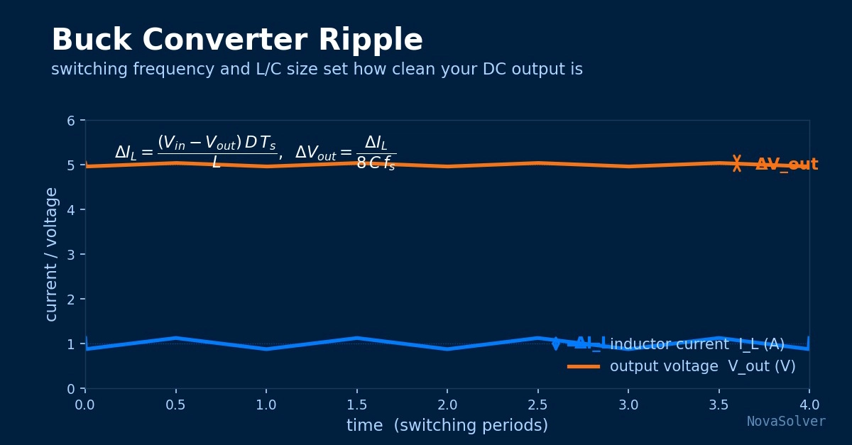
A buck converter takes a higher DC voltage and steps it down efficiently by switching a transistor on and off very fast. On a datasheet it looks clean: 12 V in, 5 V out. On an oscilloscope the output is never a flat line — it carries a small, periodic wobble called ripple. Ripple is not a defect; it is an unavoidable consequence of switching. The engineer's job is not to eliminate it but to size the inductor and output capacitor so the ripple stays within budget.
This article explains where buck-converter ripple comes from, works the numbers for a realistic design, and explains why the capacitor's parasitic resistance often matters more than its capacitance.
Why this calculation matters
Ripple is a specification, not an afterthought. Digital loads, sensitive analog circuits, and RF sections all have a maximum supply-ripple they tolerate. Exceed it and you get bit errors, elevated noise floors, or audible whine. The two components that set the ripple — the inductor and the output capacitor — are also among the largest and most expensive parts in the converter.
Oversize them and you waste board area and cost. Undersize them and the converter fails its noise spec, or the inductor saturates and the design becomes unreliable. Calculating ripple up front is how you land in between: meeting the spec without paying for margin you do not need.