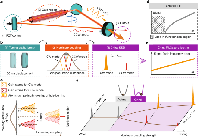
MainThe ring laser gyroscope (RLG)—as a mainstream product dominating the high-end inertial sensor market for decades3,4—has consistently played a pivotal role in ultra-high-precision inertial navigation systems, autonomous navigation platforms and even fundamental scientific facilities5,6,7,8,9,10. Distinguished from other optical gyroscopes, the RLG’s most distinctive feature lies in the integration of the light source and sensing: it is essentially a He–Ne laser, that, at the same time, produces a beat frequency proportional to the rotational rate \(\varOmega \). This beating signal originates from the Sagnac effect11,12, which causes a frequency splitting between a pair of clockwise (CW) and counterclockwise (CCW) laser modes (that is, \({\varOmega }_{{\rm{S}}}=S\varOmega /2\), where \({\varOmega }_{{\rm{S}}}\) is the mode frequency shift and S is a scale factor). However, under low rotation rates, the frequencies of the CW and CCW modes are inevitably degenerate owing to backscattering coupling13,14, which consequently leads to the loss of the beat signal. This is a fundamental challenge intrinsic to laser gyroscopes known as the lock-in effect.The current approaches for overcoming the lock-in effect involve two established techniques: the two-frequency mechanical dithered RLG1 and the magneto-optically biased four-frequency differential RLG2. However, both biasing approaches rely on external components (dithering motor and magneto-optic crystals), the reliability of which faces challenges in harsh environments (for example, deep-space exploration), as well as miniaturization and integration demands of high-precision inertial navigation devices15,16,17,18,19. An alternative self-biasing concept (that is, without external components) has been proposed20,21, exploiting intensity-dependent nonlinear interactions among asymmetric multi-longitudinal modes (for example, strong TEM00 modes and weak TEM01 modes). However, its practical implementation remains elusive due to its complex multi-mode dynamics and unresolved engineering challenges. Notably, asymmetric phenomena are ubiquitous in optical chiral systems22, which provide an additional degree of freedom for light manipulation23, computing24 and sensing25, enabling transformative applications ranging from chiral logic gates26, light–matter interactions27,28,29 and metamaterial engineering30,31 to quantum non-reciprocity control32,33. Among these diverse forms of asymmetry and chirality in nature and frontier research, this work, as shown in Fig. 1a, focuses on breaking the intensity symmetry of counter-propagating modes in a RLG under single-longitudinal-mode operation via chiral spontaneous symmetry breaking (SSB)34,35, thereby creating a fundamentally simpler, self-biased chiral laser gyroscope.Fig. 1: Operating principle of a chirality-biased He–20Ne RLG.a, The ring resonator is filled with He–20Ne single-isotope gain gas. The mirror associated with the piezoelectric transducer (PZT) enables nanometre-level cavity length tuning, with a total tuning range of over 3 μm. The intensity of the chiral CW and CCW modes can be observed from the output mirror. b, Three steps induce the chirality. First, the laser frequency is shifted towards the gain centre of the 20Ne atoms via cavity length tuning (for example, a 100 nm displacement corresponds to about 126 MHz of frequency tuning in this cavity). Second, overlapping of mirror-image spectral hole burning near the gain centre induces nonlinear mode coupling. Third, nonlinear coupling triggers chiral SSB (Icw/Iccw, the intensity of the CW or CCW laser modes). c, Key mechanism of enhanced nonlinear coupling. The CW or CCW modes are usually independently excited in distinct atomic subpopulations, while they are forced to compete for shared gain atoms within the overlap of spectral hole burning near the 20Ne gain centre. The overlap area governs the nonlinear coupling strength. d, The lock-in effect in an achiral RLG causes signal extinction at low rotation rates. e, The chiral RLG generates frequency bias through SSB, eliminating the lock-in. f, Schematic of the SSB transition from achiral (degenerate modes) to chiral state (intensity and frequency splitting modes) with increasing nonlinear coupling strength. The frequency splitting of CW and CCW laser modes \(\delta \nu \) is proportional to the intensity difference Icw – Iccw.Chiral SSBRecent studies36,37,38,39,40,41 have demonstrated that SSB can be achieved through the Kerr nonlinear effect or exceptional points in solid optical systems, and mainly focused on unidirectional light transmission or asymmetric laser emission. Here we induce SSB directly by mode competitions in a He–20Ne single-isotope gas laser (Fig. 1b,c). Contrary to the achiral RLGs restricted by the lock-in region (Fig. 1d), the chirality-biased RLG is able to break the lock-in limit by spontaneous frequency splitting (as depicted in Fig. 1e and the purple region of Fig. 1f).Using a two-parameter phase diagram analysis within a third-order nonlinear dynamic formalism42,43,44 (Methods), we theoretically demonstrate the spontaneous symmetry-breaking phenomenon in ring laser systems via numerical modelling. Figure 2a reveals the dependence of the steady-state mode intensity on the pump current Ip and \(\xi \) through the dynamic analysis; the yellow curve demarcates the parameter boundaries for SSB phase transitions in the ring laser system. Simulated results reveal that a significant intensity disparity between CW and CCW outputs occurs when both the gain and coupling strength exceed critical thresholds (as derived in the Methods), which is crucial for our chirality-biased operating principle.Fig. 2: Theoretical analysis of SSB in the ring laser.a, Phase diagram in two-parameter space (where \(\xi \) is the nonlinear coupling coefficient) demarcating symmetric (left of the yellow curve) and chiral SSB states (right). b,c, Simulated (b) and experimental (c) results of pitchfork bifurcation in CW or CCW intensities by increasing gain at \(\xi \) = 1.0015 and \({\nu =\nu }_{0}\); \({\nu }_{0}\) is the gain centre of 20Ne. d,e, Simulated (d) and experimental (e) results of pitchfork bifurcation by increasing the nonlinear coupling coefficient (or tuning frequency) at the pump current Ip = 0.6 mA. Pink background shading in b–e represents the transition from achirality to chirality. f,h, Simulations of the symmetric state (Ip = 0.4 mA) (f) and the chiral SSB state (Ip = 0.6 mA) (h). f, Phase diagram of the intensity evolution with one stable point (S0). h, Phase diagram of the intensity evolution with two stable points (S1 and S2), where \({i}_{{\rm{cw}}}\) and \({i}_{{\rm{ccw}}}\) are the minute initial intensities of the CW and CCW modes, respectively. g,i, Schematics of the evolution of the CW and CCW mode intensities from the initial to the stable state under symmetric (g) and chiral (i) SSB conditions. In both g and i, \({i}_{{\rm{cw}}}\) exceeds \({i}_{{\rm{ccw}}}\) by 0.1%. Data in c and e are presented as mean ± s.d. (n = 100 independent experiments).Source dataTo facilitate a direct comparison with experimental data, we also illustrate in Fig. 2b,d the symmetry-breaking process by varying the pump current Ip and nonlinear coupling strength \(\xi \) independently, along the dashed lines in Fig. 2a. The corresponding experimental data is shown in Fig. 2c,e, in which \(\xi \) is finely controlled by the cavity tuning. Their close agreement confirms the feasibility of inducing SSB via operational parameter optimization in He–20Ne ring lasers.Notably, Fig. 2b,c demonstrates an anomalous intensity decrease in the CCW mode with increasing gain after the phase transition, whereas the sum of the CW and CCW mode intensities still increases with the pump. To clarify this phenomenon, we numerically tracked the dynamical evolution of the CW or CCW modes before and after SSB. Figure 2f,g shows that in the symmetric phase, all trajectories converge to a unique stable fixed point, S0, located at the \({I}_{{\rm{cw}}}={I}_{{\rm{ccw}}}\) curve, regardless of the relative relationship between \({i}_{{\rm{cw}}}\) and \({i}_{{\rm{ccw}}}\) (\({i}_{{\rm{cw}}}\) and \({i}_{{\rm{ccw}}}\) denote the initial intensity of the CW and CCW laser modes respectively). By contrast, Fig. 2h reveals bistable fixed points (S1 and S2) in the chiral SSB phase, where the mode with a larger initial value will eventually form a stable strong mode as depicted by green arrows at Ip = 0.6 mA. Remarkably, as shown in Fig. 2i, a mere 0.1% initial intensity advantage of the CW mode over the CCW mode (that is, \({i}_{{\rm{cw}}}=(1+0.1 \% ){i}_{{\rm{ccw}}}\)) suffices to establish a stable CW mode-dominant state.Controlled versus random chiral SSBAs shown in Fig. 3a, to experimentally study the chiral SSB phase in a two-frequency RLG (that is, only a single longitudinal mode oscillates in both CW and CCW directions), we fabricated a triangular He–20Ne RLG with a side length of 125 mm. Its cavity supports a free spectral range of 800 MHz at 632.8 nm and is mounted horizontally on a rotation stage. A direct current power supply connected to one cathode and two anodes is used to pump the He–20Ne laser. Beat frequency signals between the CW and CCW laser modes are detected through the beam-combining prism port, whereas the other port enables the observation of CW or CCW intensity along distinct spatial directions. As shown in Fig. 3b, when the RLG operates in the chiral SSB phase, a chirality switch can be observed by a slight disturbance (for example, a sudden vibration of the platform) under stationary conditions (no rotation). This phenomenon serves as direct evidence for the existence of bistability in the chiral system. The following analysis will elucidate the switching dynamics of this bistable state under both stationary and rotating conditions.Fig. 3: Chirality switch in the chiral SSB phase of a He–20Ne RLG.a, Experimental set-up. Two methods, (1) turning the DC pump on/off and (2) rotating the stage, are applied to induce a change in the chirality. b, Existence of bistable chirality in the chiral SSB phase under the stationary condition. Data are presented as mean ± s.d. (n = 100 independent experiments). c,d, Random chirality selections observed during periodic power cycling of the RLG (c) and its corresponding statistical results (d). e,f, Regular and controllable chirality switches with uniform periodic oscillations of the RLG (e) and its corresponding statistical results (f). The statistical analyses for d and f are based on 200 experimental runs, and only the modes with higher intensity are counted in each run.Source dataFirst, a random chirality can be induced by power cycling under the stationary condition. Before the experiment, we stabilized the system in the chiral SSB phase by fixing both pump current and operating point, with the rotation stage disabled. Numerical results in Fig. 2h reveal that the final chiral state critically depends on the initial mode intensity in the chiral SSB phase. For He–Ne ring lasers, these initial conditions are fundamentally stochastic due to spontaneous emission noise. Consequently, as shown in Fig. 3c, each power restart generates random chiral output selection. To quantify this randomness, 200 consecutive power-restarting cycles are performed. Statistical analysis in Fig. 3d confirms equal probabilities for both chiral states.Second, a controllable chirality switch can be induced by the rotation. Under continuous pumping, we implement a rotational modulation by oscillating the stage with an angular speed of ±0.1 degrees per second. As shown in Fig. 3e, directional inversion of the rotational stage induces a synchronized chirality switch. Specifically, the direction of the dominant modes is consistent with the rotation direction of the RLG. Under fixed gain and operating point, 200 directional transitions are statistically analysed, revealing a near-perfect correlation between rotation direction and output chirality in Fig. 3f.Experimental demonstration of chirality-biased RLGCompared with traditional two-frequency RLGs, the beat frequency of the chiral RLG needs to be modified as equation (1): (the derivation can be found in the Methods)$$\Delta v=\sqrt{{[\eta ({I}_{{\rm{cw}}}-{I}_{{\rm{ccw}}})+2{\varOmega }_{S}]}^{2}-\left(\frac{{I}_{{\rm{cw}}}}{{I}_{{\rm{ccw}}}}+\frac{{I}_{{\rm{ccw}}}}{{I}_{{\rm{cw}}}}+2\right){r}^{2}}$$
Chiral laser gyroscopes breaking the lock-in limit - Nature
Ring laser gyroscope lock-in has been eliminated using spontaneous symmetry breaking in a He–Ne laser, enabling accurate near-zero rotation sensing without external components, improving miniaturization and precision.
6,007 words~27 min read